SEAT BELT WARNING SYSTEM Driver Side Seat Belt Warning Light does not Operate
DESCRIPTION
Tech Tips
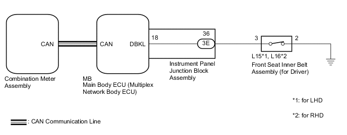
The seat belt warning light on the combination meter assembly is used for both the driver seat and front passenger seat.
The combination meter assembly blinks or turns off the seat belt warning light on the combination meter assembly in accordance with the state of the front seat inner belt assembly (for driver).
WIRING DIAGRAM
CAUTION / NOTICE / HINT
Note
The seat belt warning system uses the CAN communication system. First, confirm that there are no malfunctions in the CAN communication system. Refer to the How to Proceed with Troubleshooting procedure.
PROCEDURE
-
READ VALUE USING GTS
-
Connect the GTS to the DLC3.
-
Turn the ignition switch to ON.
-
Turn the GTS on.
-
Enter the following menus: Body Electrical / Main Body / Data List.
-
Read the Data List according to the display on the GTS.
Body Electrical > Main Body > Data ListTester Display Measurement Item Range Normal Condition Diagnostic Note D Seat Buckle SW Driver seat belt buckle switch ON or OFF ON: Driver seat belt unfastened
OFF: Driver seat belt fastened
-
Body Electrical > Main Body > Data ListTester Display D Seat Buckle SW OK The GTS display changes correctly in response to the driver seat belt condition. Result Proceed to OK NG
OK 
REPLACE COMBINATION METER ASSEMBLY except Sedan: Click here
REPLACE COMBINATION METER ASSEMBLY for Sedan: Click hereNG 
-
-
INSPECT FRONT SEAT INNER BELT ASSEMBLY (FOR DRIVER)
-
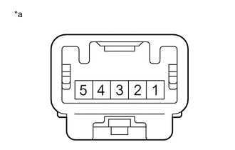
*a Component without harness connected
(Front Seat Inner Belt Assembly (for Driver))
Remove the front seat inner belt assembly (for driver).
except Sedan: Click here
for Sedan: Click here
-
Measure the resistance according to the value(s) in the table below.
Standard Resistance Tester Connection Condition Specified Condition 2 - 3 Driver seat belt unfastened Below 1 Ω 2 - 3 Driver seat belt fastened 10 kΩ or higher Result Proceed to OK NG
NG
REPLACE FRONT SEAT INNER BELT ASSEMBLY (FOR DRIVER) except Sedan: Click here
REPLACE FRONT SEAT INNER BELT ASSEMBLY (FOR DRIVER) for Sedan: Click hereOK
-
-
INSPECT INSTRUMENT PANEL JUNCTION BLOCK ASSEMBLY
-
Remove the main body ECU (multiplex network body ECU).
for LHD: Click here
for RHD: Click here
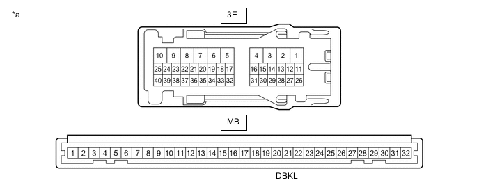
*a Component without harness connected
(Instrument Panel Junction Block Assembly)
- - -
Disconnect the 3E instrument panel junction block assembly connector.
-
Measure the resistance according to the value(s) in the table below.
Standard Resistance Tester Connection Condition Specified Condition MB-18 (DBKL) - 3E-36 Always Below 1 Ω Result Proceed to OK NG
NG
REPLACE INSTRUMENT PANEL JUNCTION BLOCK ASSEMBLY for LHD: Click here
REPLACE INSTRUMENT PANEL JUNCTION BLOCK ASSEMBLY for RHD: Click hereOK
-
-
CHECK HARNESS AND CONNECTOR (MAIN BODY ECU (MULTIPLEX NETWORK BODY ECU) - FRONT SEAT INNER BELT ASSEMBLY (FOR DRIVER) - BODY GROUND)
-
Measure the resistance according to the value(s) in the table below.
Standard Resistance for LHD Tester Connection Condition Specified Condition 3E-36 - L15-3 Always Below 1 Ω L15-3 - Body ground Always 10 kΩ or higher L15-2 - Body ground Always Below 1 Ω for RHD Tester Connection Condition Specified Condition 3E-36 - L16-3 Always Below 1 Ω L16-3 - Body ground Always 10 kΩ or higher L16-2 - Body ground Always Below 1 Ω Result Proceed to OK NG
OK
REPLACE MAIN BODY ECU (MULTIPLEX NETWORK BODY ECU) for LHD: Click here
REPLACE MAIN BODY ECU (MULTIPLEX NETWORK BODY ECU) for RHD: Click hereNG
REPAIR OR REPLACE HARNESS OR CONNECTOR
-