PRE-CRASH SAFETY SYSTEM Reverse Signal Circuit
DESCRIPTION
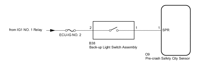
While the vehicle is driven with the shift lever in R, the buck-up light switch assembly sends a reverse signal to terminal (SPR) of the pre-crash safety city sensor. The pre-crash safety city sensor cancels pre-crash safety system when terminal (SPR) receives the reverse signal.
WIRING DIAGRAM
CAUTION / NOTICE / HINT
Note
-
Inspect the fuses for circuits related to this system before performing the following procedure.
-
When replacing the pre-crash safety city sensor, replace it with a new one and be sure to initialize the settings. If a pre-crash safety city sensor which was installed to another vehicle is used, the information stored in the pre-crash safety city sensor will not match the information from the vehicle and, as a result, a DTC may be stored.
-
If the pre-crash safety city sensor has been replaced, or the windshield glass has been replaced or removed/installed, be sure to perform Recognition Camera/Target Position Memory and Recognition Camera Axis Adjust.
PROCEDURE
-
CHECK PRE-CRASH SAFETY CITY SENSOR
-
Check pre-crash safety city sensor.
Note
DTCs may be output when connectors are disconnected during inspection. Therefore, make sure to clear the DTCs using the GTS once the inspection has been completed.
-
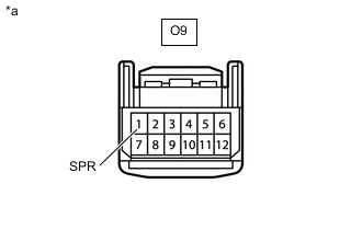
*a Front view of wire harness connector
(to Pre-crash Safety City Sensor)
Disconnect the pre-crash safety city sensor connector.
-
Measure the voltage according to the value(s) in the table below.
Standard Voltage Tester Connection Condition Specified Condition O9-1 (SPR) - Body ground Ignition switch ON, shift lever in R 11 to 14 V O9-1 (SPR) - Body ground Ignition switch ON, shift lever not in R Below 1 V
Result Proceed to OK NG -
OK 
USE SIMULATION METHOD TO CHECK Click here
NG 
-
-
CHECK HARNESS AND CONNECTOR (BACK-UP LIGHT SWITCH ASSEMBLY - PRE-CRASH SAFETY CITY SENSOR)
-
Disconnect the B38 back-up light switch assembly connector.
-
Disconnect the O9 pre-crash safety city sensor connector.
-
Measure the resistance according to the value(s) in the table below.
Standard Resistance Tester Connection Condition Specified Condition B38-1 - O9-1 (SPR) Always Below 1 Ω B38-1 - Body ground Always 10 kΩ or higher O9-1 (SPR) - Body ground Always 10 kΩ or higher Result Proceed to OK NG
NG
REPAIR OR REPLACE HARNESS OR CONNECTOR
OK
-
-
CHECK HARNESS AND CONNECTOR (BACK-UP LIGHT SWITCH ASSEMBLY POWER SORCE)
-
Disconnect the B38 back-up light switch assembly connector.
-
Measure the voltage according to the value(s) in the table below.
Standard Voltage Tester Connection Condition Specified Condition B38-2 - Body ground Ignition switch ON 11 to 14 V Result Proceed to OK NG
NG
REPAIR OR REPLACE HARNESS OR CONNECTOR
OK
-
-
INSPECT BACK-UP LIGHT SWITCH ASSEMBLY
-
Inspect the back-up light switch assembly.
for EC6A: Click here
for EA66: Click here
for EC60: Click here
for EC61: Click here
for EC69: Click here
Result Proceed to OK NG
OK
REPLACE PRE-CRASH SAFETY CITY SENSOR Click here
NG
REPLACE BACK-UP LIGHT SWITCH ASSEMBLY for EC6A: Click here
REPLACE BACK-UP LIGHT SWITCH ASSEMBLY for EA66: Click here
REPLACE BACK-UP LIGHT SWITCH ASSEMBLY for EC60: Click here
REPLACE BACK-UP LIGHT SWITCH ASSEMBLY for EC61: Click here
REPLACE BACK-UP LIGHT SWITCH ASSEMBLY for EC69: Click here -