PRE-CRASH SAFETY SYSTEM, Diagnostic DTC:C1AAF
| DTC Code | DTC Name |
|---|---|
| C1AAF | Heater Activation Relay Open |
DESCRIPTION
-
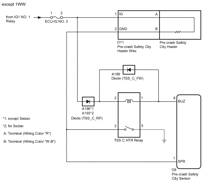
except 1WW:
The pre-crash safety city sensor controls the TSS C HTR relay to turn the pre-crash safety city heater on and off.
If the pre-crash safety city sensor detects a malfunction in the TSS C HTR relay coil circuit, it will store DTC C1AAF.
-
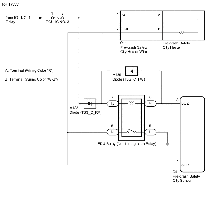
for 1WW:
The pre-crash safety city sensor controls the EDU relay (No. 1 integration relay) to turn the pre-crash safety city heater on and off.
If the pre-crash safety city sensor detects a malfunction in the EDU relay (No. 1 integration relay) coil circuit, it will store DTC C1AAF.
| DTC No. | Detection Item | DTC Detection Condition | Trouble Area |
|---|---|---|---|
| C1AAF | Heater Activation Relay Open |
Either of the following is detected: |
|
Tech Tips
Refer to Outline of Pre-crash Safety City Heater in System Description for the pre-crash safety city heater operation conditions.
WIRING DIAGRAM
CAUTION / NOTICE / HINT
Note
-
Inspect the fuses for circuits related to this system before performing the following procedure.
-
When replacing the pre-crash safety city sensor, replace it with a new one and be sure to perform initialization. If a pre-crash safety city sensor which was installed to another vehicle is used, the information stored in the pre-crash safety city sensor will not match the information from the vehicle and, as a result, a DTC may be stored.
-
If the pre-crash safety city sensor has been replaced, or the windshield glass has been replaced or removed/installed, be sure to perform Recognition Camera/Target Position Memory and Recognition Camera Axis Adjust.
PROCEDURE
-
CHECK HARNESS AND CONNECTOR (PRE-CRASH SAFETY CITY SENSOR POWER SOURCE CIRCUIT)
-
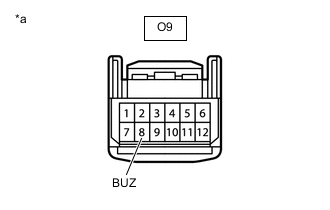
*a Front view of wire harness connector
(to Pre-crash Safety City Sensor)
Disconnect the O9 pre-crash safety city sensor connector.
Note
DTCs may be stored when connectors are disconnected during troubleshooting. Therefore, be sure to clear the DTCs using the GTS after troubleshooting has been completed.
-
Measure the voltage according to the value(s) in the table below.
Standard Voltage Tester Connection Condition Specified Condition O9-8 (BUZ) - Body ground Ignition switch ON 11 to 14 V Ignition switch off Below 1 V Result Result Proceed to OK A NG (except 1WW) B NG (for 1WW) C
B 
INSPECT TSS C HTR RELAY Click here
C
INSPECT EDU RELAY (NO. 1 INTEGRATION RELAY) Click here
A 
-
-
CHECK HARNESS AND CONNECTOR (DIODE (TSS_S_FW) CIRCUIT)
-
except 1WW:
-
Remove the TSS C HTR relay.
-
-
for 1WW:
-
Remove the EDU relay (No. 1 integration relay).
-
-
*a Front view of wire harness connector
(to Pre-crash Safety City Sensor)
Disconnect the O9 pre-crash safety city sensor connector.
Note
DTCs may be stored when connectors are disconnected during troubleshooting. Therefore, be sure to clear the DTCs using the GTS after troubleshooting has been completed.
-
Measure the voltage according to the value(s) in the table below.
Standard Voltage Tester Connection Condition Specified Condition O9-8 (BUZ) - Body ground Ignition switch ON Below 1 V Result Proceed to OK NG
OK 
REPLACE PRE-CRASH SAFETY CITY SENSOR Click here
NG
REPAIR OR REPLACE HARNESS OR CONNECTOR (DIODE (TSS_S_FW) CIRCUIT)
-
-
INSPECT TSS C HTR RELAY
-
Remove the TSS C HTR relay.
-
Inspect the TSS C HTR relay.
Result Proceed to OK NG
OK
REPAIR OR REPLACE HARNESS OR CONNECTOR (TSS C HTR RELAY COIL CIRCUIT)
NG
REPLACE TSS C HTR RELAY
-
-
INSPECT EDU RELAY (NO. 1 INTEGRATION RELAY)
-
Remove the EDU relay (No. 1 integration relay).
-
Inspect the EDU relay (No. 1 integration relay).
Result Proceed to OK NG
OK
REPAIR OR REPLACE HARNESS OR CONNECTOR (EDU RELAY (NO. 1 INTEGRATION RELAY) COIL CIRCUIT)
NG
REPLACE EDU RELAY (NO. 1 INTEGRATION RELAY) Click here
-