KNEE AIRBAG ASSEMBLY(for Sedan) INSTALLATION

PROCEDURE
-
INSTALL LOWER NO. 1 INSTRUMENT PANEL AIRBAG ASSEMBLY
-
Engage the 8 hooks to install the lower No. 1 instrument panel airbag assembly to the lower No. 1 instrument panel airbag door.
-
-
INSTALL LOWER NO. 1 INSTRUMENT PANEL AIRBAG ASSEMBLY WITH DOOR
-
Check that the ignition switch is off.
-
Check that the cable is disconnected from the negative (-) battery terminal.
CAUTION:
Wait at least 90 seconds after disconnecting the cable from the negative (-) battery terminal to disable the SRS system.
-
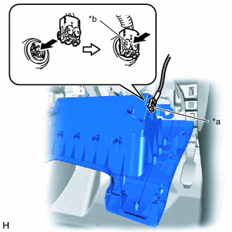
*a Airbag Connector *b Airbag Connector Lock Connect the airbag connector to the lower No. 1 instrument panel airbag assembly with door.
Note
When connecting any airbag connector, take care not to damage the airbag wire harness.
-
Push in the airbag connector lock to install the airbag connector.
-
Engage the 7 claws and 2 guides to temporarily install the lower No. 1 instrument panel airbag assembly with door.
-
Install the 4 bolts.
- Torque:
- 10 N*m { 102 kgf*cm, 7 ft.*lbf }
Note
Confirm that the lower No. 1 instrument panel airbag assembly with door is installed securely without any excessive gaps and is not protruding outward.
-
-
INSTALL NO. 1 INSTRUMENT PANEL UNDER COVER SUB-ASSEMBLY (w/ Instrument Panel Under Cover)
-
INSTALL NO. 1 SWITCH HOLE BASE (for LHD)
-
INSTALL NO. 1 SWITCH HOLE BASE (for RHD)
-
INSTALL NO. 2 SWITCH HOLE BASE (for RHD without Entry and Start System)
-
INSTALL INSTRUMENT CLUSTER FINISH PANEL ASSEMBLY
-
INSTALL NO. 1 INSTRUMENT PANEL REGISTER SUB-ASSEMBLY
-
INSTALL NO. 2 INSTRUMENT PANEL GARNISH SUB-ASSEMBLY
-
INSTALL LOWER INSTRUMENT CLUSTER FINISH PANEL ASSEMBLY (for LHD)
-
INSTALL LOWER INSTRUMENT CLUSTER FINISH PANEL ASSEMBLY (for RHD)
-
INSTALL NO. 2 INSTRUMENT PANEL REGISTER SUB-ASSEMBLY
-
INSTALL CENTER INSTRUMENT CLUSTER FINISH PANEL SUB-ASSEMBLY
-
INSTALL NO. 1 INSTRUMENT PANEL GARNISH SUB-ASSEMBLY
-
CONNECT CABLE TO NEGATIVE BATTERY TERMINAL
Note
When disconnecting the cable, some systems need to be initialized after the cable is reconnected.
-
PERFORM DIAGNOSTIC SYSTEM CHECK
-
INSPECT SRS WARNING LIGHT