SPIRAL CABLE(w/o VSC) INSTALLATION
PROCEDURE
-
INSTALL SPIRAL CABLE SUB-ASSEMBLY
-
Check that the ignition switch is off.
-
Check that the cable is disconnected from the negative (-) battery terminal.
CAUTION:
Wait at least 90 seconds after disconnecting the cable from the negative (-) battery terminal to disable the SRS system.
-
Check that the front wheels are facing straight ahead.
-
Set the turn signal switch to the neutral position.
Note
If it is not in the neutral position, the turn signal switch pin may break.
-
Engage the 3 claws to install the spiral cable sub-assembly.
-
Connect each connector.
-
-
INSTALL STEERING COLUMN COVER
-
INSPECT AND ADJUST SPIRAL CABLE SUB-ASSEMBLY
-
Check that the ignition switch is off.
-
Check that the cable is disconnected from the negative (-) battery terminal.
CAUTION:
Wait at least 90 seconds after disconnecting the cable from the negative (-) battery terminal to disable the SRS system.
-
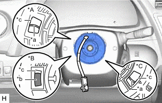
*A Flat Cable Type without Steering Heater *B Colored Roller Type *C Flat Cable Type with Steering Heater *a Flat Cable *b Colored Roller *c Inspection Window Check if the spiral cable sub-assembly is centered.
-
The connector is positioned at the top.
-
The colored roller or flat cable can be seen in the inspection window.
OK:
-
-
If the spiral cable sub-assembly is not centered, center it.
Note
Make sure to observe the following precautions, otherwise the spiral cable sub-assembly may be damaged.
-
Do not rotate the spiral cable sub-assembly with the battery connected and the ignition switch ON.
-
Release the interlock before rotating the spiral cable sub-assembly.
-
Do not rotate the spiral cable sub-assembly using the airbag wire harness.
-
Do not rotate the spiral cable sub-assembly with excessive force.
-
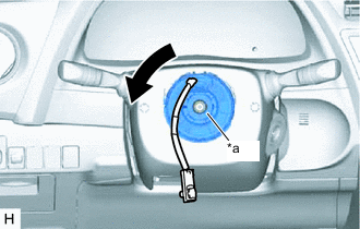
*a Interlock While pushing on the interlock shown in the illustration, rotate the spiral cable sub-assembly counterclockwise slowly by hand until it stops.
Note
If the spiral cable sub-assembly is rotated clockwise in this step, it may be damaged and may no longer be able to be centered. Make sure to only rotate the spiral cable sub-assembly counterclockwise.
Tech Tips
If the interlock is engaged, the spiral cable sub-assembly will lock when the connector is near at the top or bottom of the rotation of the spiral cable sub-assembly.
-
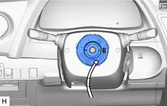
If the connector is not positioned at the bottom of the rotation of the spiral cable sub-assembly when the spiral cable sub-assembly is turned until it stops, turn the spiral cable sub-assembly clockwise until the connector is positioned at the bottom as shown in the illustration.
-
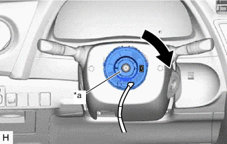
*a Interlock While pushing on the interlock shown in the illustration, rotate the spiral cable sub-assembly clockwise approximately 2.5 times.
Note
If the spiral cable sub-assembly is rotated clockwise 5 times or more from the point at which it stops and the connector is positioned at the bottom, the spiral cable sub-assembly may be damaged.
Tech Tips
If the interlock is engaged, the spiral cable sub-assembly will lock when the connector is near at the top or bottom of the rotation of the spiral cable sub-assembly.
-
*A Flat Cable Type without Steering Heater *B Colored Roller Type *C Flat Cable Type with Steering Heater *a Flat Cable *b Colored Roller *c Inspection Window Check that the spiral cable sub-assembly is centered.
-
The connector is positioned at the top.
-
The colored roller or flat cable can be seen in the inspection window.
OK:
Note
If the spiral cable sub-assembly cannot be centered, it may be damaged. Replace the spiral cable sub-assembly with a new one.
-
-
-
-
ALIGN FRONT WHEELS FACING STRAIGHT AHEAD
-
INSTALL STEERING WHEEL ASSEMBLY