AIRBAG SYSTEM Trouble in Passenger Airbag ON/OFF Indicator
DESCRIPTION
This circuit detects the airbag cut off switch cylinder sub-assembly status.
The passenger airbag ON/OFF indicator comes on to inform the front passenger airbag status (activated or deactivated).
Tech Tips
Approximately 6 seconds after the ignition switch is turned to ON, the passenger airbag ON/OFF indicator will indicate ON/OFF depending on the conditions listed below.
| Airbag Cut Off Switch Cylinder Sub-assembly | Passenger Airbag ON/OFF Indicator | SRS Warning Light | |
|---|---|---|---|
| ON Indicator | OFF Indicator | ||
| ON | ON | OFF | OFF |
| OFF | OFF | ON | OFF |
| Switch failure | OFF | ON | ON |
WIRING DIAGRAM
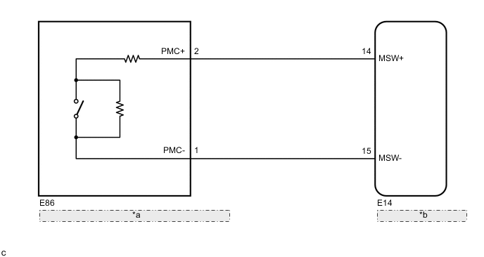
| *a | Airbag Cut Off Switch Cylinder Sub-assembly |
| *b | Airbag Sensor Assembly |
CAUTION / NOTICE / HINT
Note
After turning the ignition switch off, waiting time may be required before disconnecting the cable from the negative (-) battery terminal. Therefore, make sure to read the disconnecting the cable from the negative (-) battery terminal notices before proceeding with work.
PROCEDURE
-
CHECK SRS WARNING LIGHT
-
Turn the ignition switch to ON, and check the SRS warning light condition.
OK After the primary check period, the SRS warning light goes off. Tech Tips
-
If the SRS warning light is on when this malfunction occurs, a DTC is stored. Troubleshoot for the stored DTC.
-
The primary check period is approximately 6 seconds after the ignition switch is turned to ON.
Result Proceed to OK NG -
NG 
GO TO DIAGNOSTIC TROUBLE CODE CHART Click here
OK 
-
-
CHECK CONNECTORS
-
Turn the ignition switch off.
-
Disconnect the cable from the negative (-) battery terminal.
CAUTION:
Wait at least 90 seconds after disconnecting the cable from the negative (-) battery terminal to disable the SRS system.
-
Check that the connectors are properly connected to the airbag sensor assembly and airbag cut off switch cylinder sub-assembly.
OK The connectors are properly connected. Tech Tips
If the connectors are not properly connected, reconnect the connectors and proceed to the next inspection.
-
Disconnect the connectors from the airbag sensor assembly and airbag cut off switch cylinder sub-assembly.
-
Check that the terminals of the connectors are not damaged.
OK The terminals are not deformed or damaged. Result Proceed to OK NG
NG
REPLACE INSTRUMENT PANEL WIRE
OK
-
-
CHECK INSTRUMENT PANEL WIRE (OPEN)
-
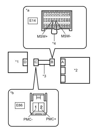
*1 Airbag Cut Off Switch Cylinder Sub-assembly *2 Airbag Sensor Assembly *3 Instrument Panel Wire *4 Service Wire *a Front view of wire harness connector
(to Airbag Sensor Assembly)
*b Front view of wire harness connector
(to Airbag Cut Off Switch Cylinder Sub-assembly)
Using a service wire, connect terminals 14 (MSW+) and 15 (MSW-) of connector B.
Note
Do not forcibly insert the service wire into the terminals of the connector when connecting the wire.
-
Measure the resistance according to the value(s) in the table below.
Standard Resistance Tester Connection Condition Specified Condition E86-2 (PMC+) - E86-1 (PMC-) Always Below 1 Ω -
Disconnect the service wire from connector B.
Result Proceed to OK NG
NG
REPLACE INSTRUMENT PANEL WIRE
OK
-
-
CHECK INSTRUMENT PANEL WIRE (SHORT)
-
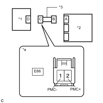
*1 Airbag Cut Off Switch Cylinder Sub-assembly *2 Airbag Sensor Assembly *3 Instrument Panel Wire *a Front view of wire harness connector
(to Airbag Cut Off Switch Cylinder Sub-assembly)
Measure the resistance according to the value(s) in the table below.
Standard Resistance Tester Connection Condition Specified Condition E86-2 (PMC+) - E86-1 (PMC-) Always 1 MΩ or higher Result Proceed to OK NG
NG
REPLACE INSTRUMENT PANEL WIRE
OK
-
-
CHECK INSTRUMENT PANEL WIRE (SHORT TO B+)
-
*1 Airbag Cut Off Switch Cylinder Sub-assembly *2 Airbag Sensor Assembly *3 Instrument Panel Wire *a Front view of wire harness connector
(to Airbag Cut Off Switch Cylinder Sub-assembly)
Connect the cable to the negative (-) battery terminal.
-
Turn the ignition switch to ON.
-
Measure the voltage according to the value(s) in the table below.
Standard Voltage Tester Connection Condition Specified Condition E86-2 (PMC+) - Body ground Ignition switch ON Below 1 V E86-1 (PMC-) - Body ground Ignition switch ON Below 1 V -
Turn the ignition switch off.
-
Disconnect the cable from the negative (-) battery terminal.
CAUTION:
Wait at least 90 seconds after disconnecting the cable from the negative (-) battery terminal to disable the SRS system.
Result Proceed to OK NG
NG
REPLACE INSTRUMENT PANEL WIRE
OK
-
-
CHECK INSTRUMENT PANEL WIRE (SHORT TO GROUND)
-
*1 Airbag Cut Off Switch Cylinder Sub-assembly *2 Airbag Sensor Assembly *3 Instrument Panel Wire *a Front view of wire harness connector
(to Airbag Cut Off Switch Cylinder Sub-assembly)
Measure the resistance according to the value(s) in the table below.
Standard Resistance Tester Connection Condition Specified Condition E86-2 (PMC+) - Body ground Always 1 MΩ or higher E86-1 (PMC-) - Body ground Always 1 MΩ or higher Result Proceed to OK NG
NG
REPLACE INSTRUMENT PANEL WIRE
OK
-
-
CHECK AIRBAG CUT OFF SWITCH CYLINDER SUB-ASSEMBLY
-
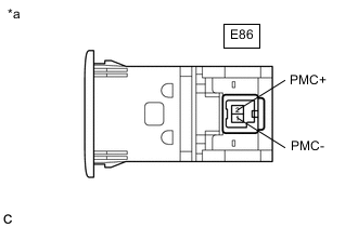
*a Component without harness connected
(Airbag Cut Off Switch Cylinder Sub-assembly)
Measure the resistance according to the value(s) in the table below.
Standard Resistance Tester Connection Condition Specified Condition E86-2 (PMC+) - E86-1 (PMC-) Cut off switch is ON 360 to 440 Ω E86-2 (PMC+) - E86-1 (PMC-) Cut off switch is OFF 90 to 110 Ω Result Proceed to OK NG
OK
REPLACE AIRBAG SENSOR ASSEMBLY Click here
NG
REPLACE AIRBAG CUT OFF SWITCH CYLINDER SUB-ASSEMBLY Click here
-