IMMOBILISER SYSTEM(w/o Entry and Start System) Key Cannot be Registered
DESCRIPTION
A maximum of 5 master key ID codes and 3 sub key ID codes can be registered.
WIRING DIAGRAM
CAUTION / NOTICE / HINT
Note
If the transponder key ECU assembly is replaced, refer to Service Bulletin.
PROCEDURE
-
CHECK REGISTRATION MODE
-
Check that the system enters registration mode.
OK System enters registration mode. Result Proceed to OK NG
NG 
INSPECT UNLOCK WARNING SWITCH ASSEMBLY Click here
OK 
-
-
CHECK SECURITY INDICATOR LIGHT OPERATION
-
In registration mode, insert the key into the ignition key cylinder and check the security indicator light.
Tech Tips
If the new key ID code registration fails, code 2-1 will be output through the security light. Trying to re-register an already registered key will cause code 2-2 to be output when the key is inserted. If the number of registered key ID codes exceeds the maximum limit, code 2-3 will be output through the security indicator light. The output details are shown in the following illustration.
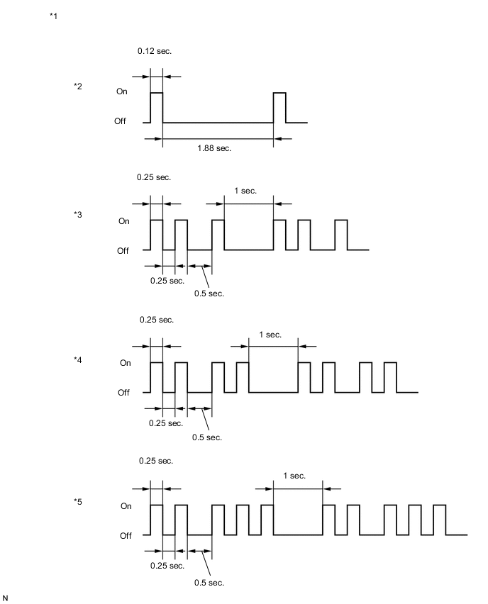
*1 Security Indicator Light *2 Normal (Immobiliser system is operating normally) *3 Code 2-1 *4 Code 2-2 *5 Code 2-3 - - Result Result Proceed to Code 2-1 or Code 2-3 is output A Code 2-2 is output B
B 
END (REGISTERED KEY WAS USED)
A
-
-
READ VALUE USING GTS (TRANSPONDER S-CODE, TRANSPONDER M-CODE)
-
Connect the GTS to the DLC3.
-
Turn the ignition switch to ON.
-
Turn the GTS on.
-
Enter the following menus: Body Electrical / Immobiliser / Data List.
-
Read the Data List according to the display on the GTS.
Body Electrical > Immobiliser > Data ListTester Display Measurement Item Range Normal Condition Diagnostic Note Transponder S-code Number of registered sub key min. 0, max. 15 Number of registered sub key - Transponder M-code Number of registered master key min. 0, max. 15 Number of registered master key -
Body Electrical > Immobiliser > Data ListTester Display Transponder S-code Transponder M-code Result Result Proceed to 5 is displayed for "Transponder M-code" and 0 is displayed for "Transponder S-code" A 0 is displayed for "Transponder M-code" and 3 is displayed for "Transponder S-code" B 5 is displayed for "Transponder M-code" and 3 is displayed for "Transponder S-code" C Values are other than above D
A
KEY REGISTRATION (SUB-KEY)
B
KEY REGISTRATION (MASTER KEY)
C
MAXIMUM NUMBER OF KEYS ALREADY REGISTERED
D
-
-
KEY REGISTRATION
-
Refer to the table below to determine if additional keys can be registered.
Number of Keys Registered (Master and Sub) Proceed to 0 New key ID code registration 1 to 7 Additional key ID code registration -
Check if an additional key can be registered.
OK Additional key can be registered. Result Proceed to OK NG
OK
END (KEY MALFUNCTION)
NG
REPLACE TRANSPONDER KEY ECU ASSEMBLY
-
-
INSPECT UNLOCK WARNING SWITCH ASSEMBLY
-
Remove the unlock warning switch assembly.
-
Inspect the unlock warning switch assembly.
Result Proceed to OK NG
NG
REPLACE UNLOCK WARNING SWITCH ASSEMBLY Click here
OK
-
-
CHECK HARNESS AND CONNECTOR (TRANSPONDER KEY ECU ASSEMBLY - UNLOCK WARNING SWITCH ASSEMBLY)
-
Disconnect the E5 unlock warning switch assembly connector.
-
Disconnect the E21 transponder key ECU assembly connector.
-
Measure the resistance according to the value(s) in the table below.
Standard Resistance Tester Connection Condition Specified Condition E5-1 - E21-3 (KSW) Always Below 1 Ω E5-2 - Body ground Always Below 1 Ω E5-1 - Body ground Always 10 kΩ or higher E21-3 (KSW) - Body ground Always 10 kΩ or higher Result Proceed to OK NG
OK
REPLACE TRANSPONDER KEY ECU ASSEMBLY
NG
REPAIR OR REPLACE HARNESS OR CONNECTOR
-