ENTRY AND START SYSTEM(for Start Function), Diagnostic DTC:B2284
| DTC Code | DTC Name |
|---|---|
| B2284 | Brake Signal Malfunction |
DESCRIPTION
This DTC is stored when the brake signal sent via direct line and the brake signal sent via CAN communication do not match.
Tech Tips
When the cable is disconnected and reconnected to the negative (-) battery terminal, the power source mode returns to the state it was in before the cable was disconnected.
| DTC No. | Detection Item | DTC Detection Condition | Trouble Area | Note |
|---|---|---|---|---|
| B2284 | Brake Signal Malfunction | The brake signal sent via direct line and the brake signal sent via CAN communication (1-trip detection logic*) do not match. |
|
Connect the cable to the negative (-) battery terminal, release the brake pedal and wait 20 seconds or more. Then depress the brake pedal for 20 seconds or more. |
-
*: Only detected while a malfunction is present and the engine switch is on (IG)
| Vehicle Condition when Malfunction Detected | Fail-safe Function when Malfunction Detected |
|---|---|
| With the electrical key transmitter sub-assembly in the cabin, even if an engine start operation is performed, the engine does not start (the indicator in the combination meter is not illuminated). However, the engine can be started by turning the engine switch on (ACC) and then pressing and holding it.
|
- |
| DTC No. | Data List Item | Active Test Item |
|---|---|---|
| B2284 |
Power Source Control
ABS/VSC/TRAC |
- |
WIRING DIAGRAM
Figure 1. except Sedan
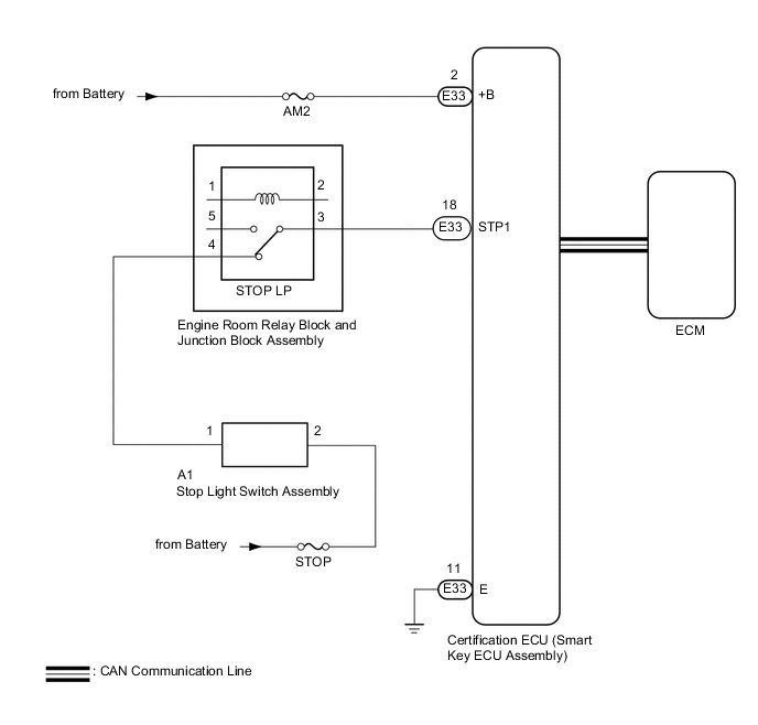
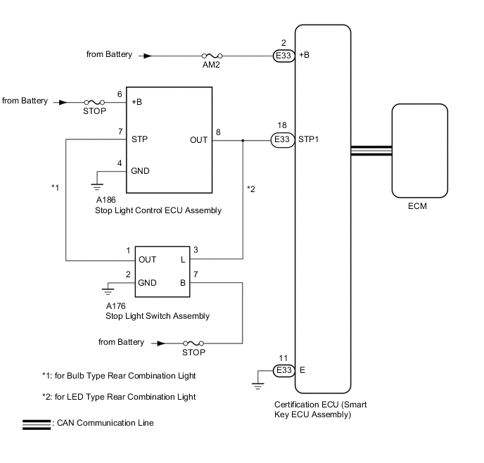
Figure 2. for Sedan
CAUTION / NOTICE / HINT
Tech Tips
Check the connector connection to the terminal to make sure that there is no abnormality such as a loose connection, deformation, etc.
Note
-
When using the GTS with the engine switch off, connect the GTS to the DLC3 and turn a courtesy light switch on and off at intervals of 1.5 seconds or less until communication between the GTS and the vehicle begins. Then select the Model Code "KEY REGIST" under manual mode and enter the following menus: Body Electrical / Entry&Start(CAN). While using the GTS, periodically turn a courtesy light switch on and off at intervals of 1.5 seconds or less to maintain communication between the GTS and the vehicle.
-
The entry and start system (for Start Function) uses the CAN communication system and LIN communication system. First inspect the communication systems by following How to Proceed with Troubleshooting. Troubleshoot the entry and start system (for Start Function) after confirming that the communication systems are functioning properly.
-
Before replacing the certification ECU (smart key ECU assembly), refer to entry and start system (for Start Function) Precaution.
-
Inspect the fuses of circuits related to this system before performing the following procedure.
-
After performing repairs, perform the operation that fulfills the DTC output confirmation operation, and then confirm that no DTCs are output again.
PROCEDURE
-
READ VALUE USING GTS (STOP LIGHT SWITCH1)
-
Connect the GTS to the DLC3.
-
Turn the engine switch on (IG).
-
Turn the GTS on.
-
Enter the following menus: Body Electrical / Power Source Control / Data List.
-
Read the Data List according to the display on the GTS.
Body Electrical > Power Source Control > Data ListTester Display Measurement Item Range Normal Condition Diagnostic Note Stop Light Switch1 State of brake pedal ON or OFF ON: Brake pedal depressed
OFF: Brake pedal released
-
Use this item to determine whether the stop light switch is malfunctioning.
-
The engine cannot be started when this item is OFF.
-
When this item is malfunctioning, the engine can be started by pressing and holding the engine switch for a certain period of time.
Body Electrical > Power Source Control > Data ListTester Display Stop Light Switch1 OK ON (brake pedal is depressed) and OFF (brake pedal is released) appear on the screen. Result Result Proceed to NG A OK (for 1NR-FE) B OK (for 1ZR-FAE) C OK (for 1ND-TV) D OK (for 8AR-FTS) E OK (for 1ZR-FE) F OK (for 2ZR-FE) G -
B 
GO TO SFI SYSTEM (HOW TO PROCEED WITH TROUBLESHOOTING) Click here
C
GO TO SFI SYSTEM (HOW TO PROCEED WITH TROUBLESHOOTING) Click here
D
GO TO ECD SYSTEM (HOW TO PROCEED WITH TROUBLESHOOTING) Click here
E
GO TO SFI SYSTEM (HOW TO PROCEED WITH TROUBLESHOOTING) Click here
F
GO TO SFI SYSTEM (HOW TO PROCEED WITH TROUBLESHOOTING) Click here
G
GO TO SFI SYSTEM (HOW TO PROCEED WITH TROUBLESHOOTING) Click here
A 
-
-
CHECK HARNESS AND CONNECTOR (POWER SOURCE)
Result Proceed to OK NG
-
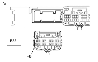
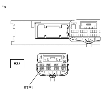
*a Rear view of wire harness connector
(to Certification ECU (smart key ECU assembly))
Disconnect the E33 certification ECU (smart key ECU assembly) connector.
-
Measure the voltage according to the value(s) in the table below.
Standard Voltage Tester Connection Condition Specified Condition E33-2 (+B) - Body ground Always 11 to 14 V Result Proceed to OK NG
NG
REPAIR OR REPLACE HARNESS OR CONNECTOR IN CIRCUIT CONNECTED TO POWER SOURCE
OK
-
-
CHECK HARNESS AND CONNECTOR (GROUND)
Result Proceed to OK NG
-
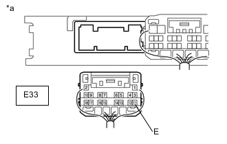
*a Rear view of wire harness connector
(to Certification ECU (smart key ECU assembly))
Measure the resistance according to the value(s) in the table below.
Standard Resistance Tester Connection Condition Specified Condition E33-11 (E) - Body ground Always Below 1 Ω Result Proceed to OK NG
NG
REPAIR OR REPLACE HARNESS OR CONNECTOR
OK
-
-
SYSTEM CHECK
-
Check the vehicle specification.
Result Result Proceed to except Sedan A for Sedan B
B 
CHECK HARNESS AND CONNECTOR (STOP LIGHT SWITCH ASSEMBLY (POWER SOURCE, GROUND)) Click here
A
-
-
INSPECT STOP LP RELAY
-
Remove the STOP LP relay.
-
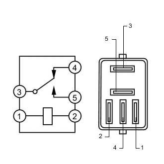
Measure the resistance according to the value(s) in the table below.
Standard Resistance Tester Connection Condition Specified Condition 3 - 4 Voltage is not applied between terminals 1 and 2 Below 1 Ω 3 - 5 10 kΩ or higher 3 - 4 Voltage is applied between terminals 1 and 2 10 kΩ or higher 3 - 5 Below 1 Ω Result Proceed to OK NG
NG
REPLACE STOP LP RELAY
OK
-
-
INSPECT STOP LIGHT SWITCH ASSEMBLY
Result Proceed to OK NG
NG
REPLACE STOP LIGHT SWITCH ASSEMBLY Click here
OK
-
CHECK HARNESS AND CONNECTOR (CERTIFICATION ECU (SMART KEY ECU ASSEMBLY) - STOP LIGHT SWITCH ASSEMBLY)
-
Disconnect the A1 stop light switch assembly connector.
-
*a Rear view of wire harness connector
(to Certification ECU (Smart Key ECU Assembly))
Measure the resistance according to the value(s) in the table below.
Standard Resistance Tester Connection Condition Specified Condition E33-18 (STP1) - A1-1 Always Below 1 Ω E33-18 (STP1) or A1-1 - Body ground Always 10 kΩ or higher -
Reconnect the A1 stop light switch assembly connector.
-
Measure the voltage according to the value(s) in the table below.
Standard Voltage Tester Connection Condition Specified Condition E33-18 (STP1) - Body ground Brake pedal released 1 V or less Brake pedal depressed 9 V or higher Result Proceed to OK NG
OK
REPLACE CERTIFICATION ECU (SMART KEY ECU ASSEMBLY)
NG
REPAIR OR REPLACE HARNESS OR CONNECTOR
-
-
CHECK HARNESS AND CONNECTOR (STOP LIGHT SWITCH ASSEMBLY (POWER SOURCE, GROUND))
-
Disconnect the A176 stop light switch assembly connector.
-
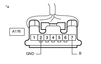
*a Front view of wire harness connector
(to Stop Light Switch Assembly)
Measure the voltage according to the value(s) in the table below.
Standard Voltage Tester Connection Condition Specified Condition A176-7 (B) - Body ground Always 11 to 14 V -
Measure the resistance according to the value(s) in the table below.
Standard Resistance Tester Connection Condition Specified Condition A176-2 (GND) - Body ground Always Below 1 Ω Result Proceed to OK NG
NG
REPAIR OR REPLACE HARNESS OR CONNECTOR
OK
-
-
INSPECT STOP LIGHT SWITCH ASSEMBLY
Result Proceed to OK NG
NG
REPLACE STOP LIGHT SWITCH ASSEMBLY Click here
OK
-
SYSTEM CHECK
-
Check the vehicle specification.
Result Result Proceed to for Bulb Type Rear Combination Light A for LED Type Rear Combination Light B
B
CHECK HARNESS AND CONNECTOR (CERTIFICATION ECU (SMART KEY ECU ASSEMBLY) - STOP LIGHT SWITCH ASSEMBLY) Click here
A
-
-
CHECK HARNESS AND CONNECTOR (STOP LIGHT CONTROL ECU ASSEMBLY - STOP LIGHT SWITCH ASSEMBLY)
-
Disconnect the A176 stop light switch assembly connector.
-
Disconnect the A186 stop light control ECU assembly connector.
-
Measure the resistance according to the value(s) in the table below.
Standard Resistance Tester Connection Condition Specified Condition A186-7 (STP) - A176-1 (OUT) Always Below 1 Ω A186-7 (STP) or A176-1 (OUT) - Body ground Always 10 kΩ or higher Result Proceed to OK NG
NG
REPAIR OR REPLACE HARNESS OR CONNECTOR
OK
-
-
CHECK HARNESS AND CONNECTOR (STOP LIGHT CONTROL ECU ASSEMBLY (POWER SOURCE, GROUND))
-
Disconnect the A186 stop light control ECU assembly connector.
-
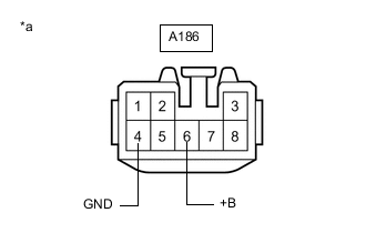
*a Front view of wire harness connector
(to Stop Light control ECU Assembly)
Measure the voltage according to the value(s) in the table below.
Standard Voltage Tester Connection Condition Specified Condition A186-6 (B) - Body ground Always 11 to 14 V -
Measure the resistance according to the value(s) in the table below.
Standard Resistance Tester Connection Condition Specified Condition A186-4 (GND) - Body ground Always Below 1 Ω Result Proceed to OK NG
NG
REPAIR OR REPLACE HARNESS OR CONNECTOR
OK
-
-
INSPECT STOP LIGHT CONTROL ECU ASSEMBLY
Result Proceed to OK NG
NG
REPLACE STOP LIGHT CONTROL ECU ASSEMBLY Click here
OK
-
CHECK HARNESS AND CONNECTOR (CERTIFICATION ECU (SMART KEY ECU ASSEMBLY) - STOP LIGHT CONTROL ECU ASSEMBLY)
-
Disconnect the A186 stop light control ECU assembly connector.
-
Disconnect the E33 certification ECU (smart key ECU assembly) connector.
-
Measure the resistance according to the value(s) in the table below.
Standard Resistance Tester Connection Condition Specified Condition E33-18 (STP1) - A186-8 (OUT) Always Below 1 Ω E33-18 (STP1) or A186-8 (OUT) - Body ground Always 10 kΩ or higher Result Proceed to OK NG
OK
REPLACE CERTIFICATION ECU (SMART KEY ECU ASSEMBLY)
NG
REPAIR OR REPLACE HARNESS OR CONNECTOR
-
-
CHECK HARNESS AND CONNECTOR (CERTIFICATION ECU (SMART KEY ECU ASSEMBLY) - STOP LIGHT SWITCH ASSEMBLY)
-
Disconnect the A176 stop light switch assembly connector.
-
Disconnect the E33 certification ECU (smart key ECU assembly) connector.
-
Measure the resistance according to the value(s) in the table below.
Standard Resistance Tester Connection Condition Specified Condition E33-18 (STP1) - A176-3 (L) Always Below 1 Ω E33-18 (STP1) or A176-3 (L) - Body ground Always 10 kΩ or higher Result Proceed to OK NG
OK
REPLACE CERTIFICATION ECU (SMART KEY ECU ASSEMBLY)
NG
REPAIR OR REPLACE HARNESS OR CONNECTOR
-