ENTRY AND START SYSTEM(for Start Function), Diagnostic DTC:B2282, B2283
| DTC Code | DTC Name |
|---|---|
| B2282 | Vehicle Speed Signal Malfunction |
| B2283 | Vehicle Speed Sensor Malfunction |
DESCRIPTION
DTC B2282 is stored when the vehicle speed signal sent by the combination meter assembly via direct line and the vehicle speed signal sent via CAN communication do not match.
DTC B2283 is stored when a malfunction in the vehicle speed sensor is detected.
Tech Tips
When the cable is disconnected and reconnected to the negative (-) battery terminal, the power source mode returns to the state it was in before the cable was disconnected.
| DTC No. | Detection Item | DTC Detection Condition | Trouble Area | Note |
|---|---|---|---|---|
| B2282 | Vehicle Speed Signal Malfunction | The vehicle speed signal sent by the combination meter assembly via direct line and the vehicle speed signal sent via CAN communication (1-trip detection logic*) do not match. |
|
Drive the vehicle for 20 seconds at a vehicle speed of 25 km/h (16 mph) or more, and then drive the vehicle at a vehicle speed of less than 5 km/h (3 mph) for 20 seconds. |
| B2283 | Vehicle Speed Sensor Malfunction | Either of the of the following malfunctions is detected (a vehicle speed sensor malfunction is detected) (1-trip detection logic*)
|
|
Run the engine at an engine speed of 2000 rpm or more for 330 seconds. |
-
*: Only detected while a malfunction is present and the engine switch is on (IG)
| DTC Code | Vehicle Condition when Malfunction Detected | Fail-safe Function when Malfunction Detected |
|---|---|---|
| B2282 |
|
- |
| B2283 |
|
- |
| DTC No. | Data List Item | Active Test Item |
|---|---|---|
| B2282 B2283 |
Power Source Control
Starting Control
Combination Meter |
- |
WIRING DIAGRAM
Figure 1. for 1NR-FE
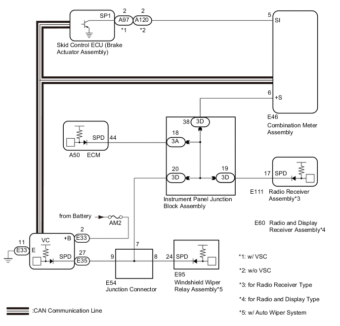
Figure 2. for 1ZR-FAE
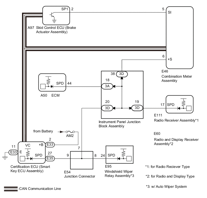
Figure 3. for 1ND-TV
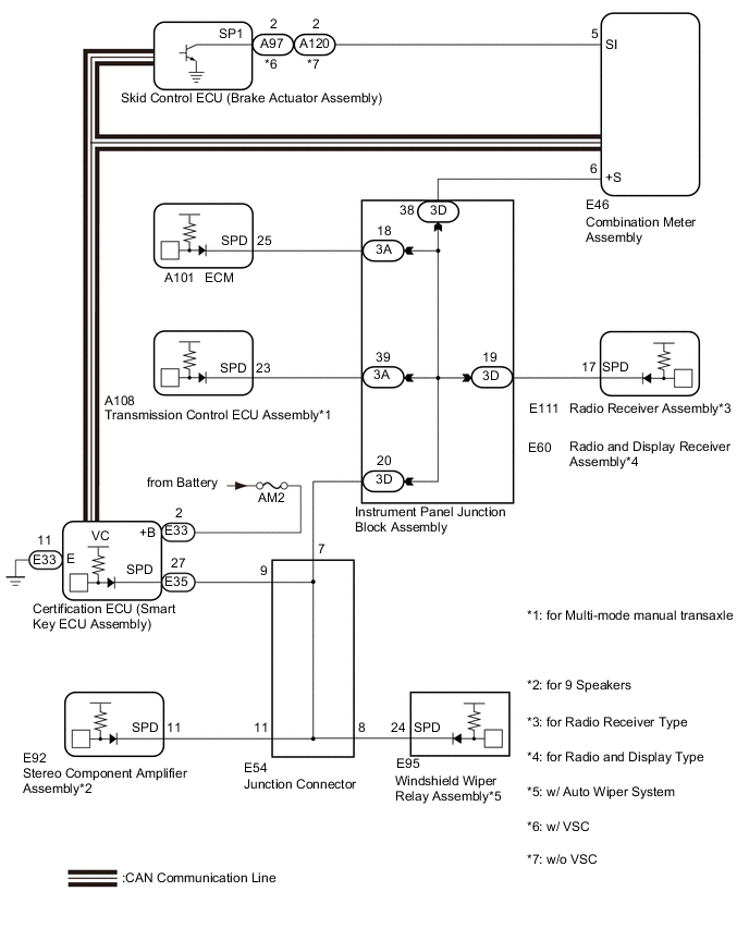
Figure 4. for 1WW
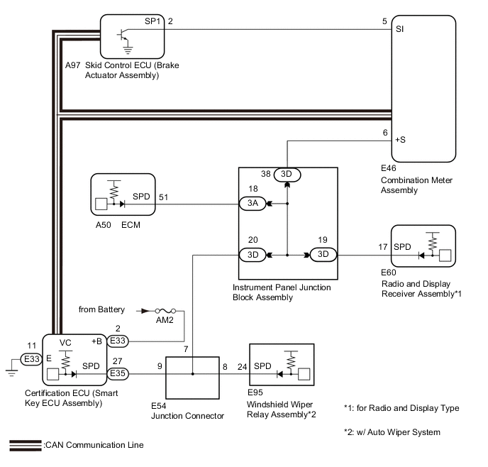
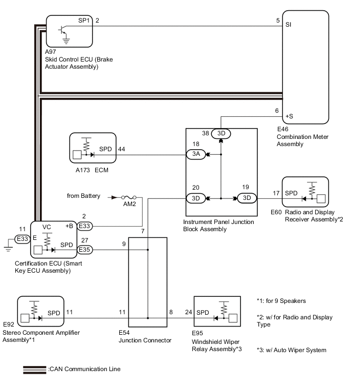
Figure 5. for 1ZR-FE or 2ZR-FE
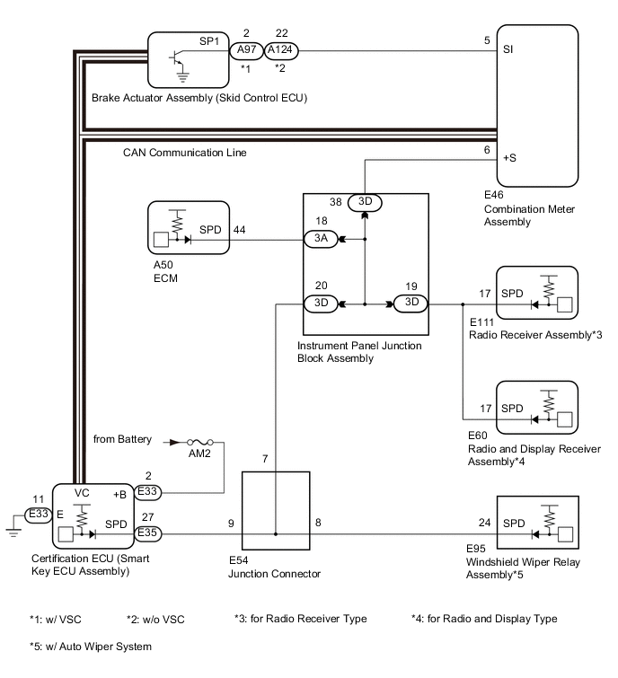
Figure 6. for 8AR-FTS
Tech Tips
-
A voltage of 12 V or 5 V is output from each ECU and then input to the combination meter. The signal is changed to a pulse signal at the transistor in the combination meter. Each ECU controls the respective system based on the pulse signal.
-
If a short occurs in an ECU, all systems in the diagram above will not operate normally.
CAUTION / NOTICE / HINT
Note
-
When using the GTS with the engine switch off, connect the GTS to the DLC3 and turn a courtesy light switch on and off at intervals of 1.5 seconds or less until communication between the GTS and the vehicle begins. Then select the Model Code "KEY REGIST" under manual mode and enter the following menus: Body Electrical / Entry&Start(CAN). While using the GTS, periodically turn a courtesy light switch on and off at intervals of 1.5 seconds or less to maintain communication between the GTS and the vehicle.
-
The entry and start system (for Start Function) uses the CAN communication system and LIN communication system. First inspect the communication systems by following How to Proceed with Troubleshooting. Troubleshoot the entry and start system (for Start Function) after confirming that the communication systems are functioning properly.
-
Before replacing the certification ECU (smart key ECU assembly), refer to entry and start system (for Start Function) Precaution.
-
Inspect the fuses of circuits related to this system before performing the following procedure.
-
After performing repairs, perform the operation that fulfills the DTC output confirmation operation, and then confirm that no DTCs are output again.
PROCEDURE
-
READ VALUE USING GTS (VEHICLE SPEED METER)
-
Connect the GTS to the DLC3.
-
Turn the engine switch on (IG).
-
Turn the GTS on.
-
Enter the following menus: Body Electrical / Combination Meter / Data List.
-
Check the Data List for proper functioning of the vehicle speed signal.
Body Electrical > Combination Meter > Data ListTester Display Measurement Item Range Normal Condition Diagnostic Note Vehicle Speed Meter Vehicle speed Min.: 0, Max.: 255 Almost same as actual vehicle speed (Speedometer tester) -
Body Electrical > Combination Meter > Data ListTester Display Vehicle Speed Meter OK Vehicle speed displayed on the GTS is almost the same as the actual vehicle speed measured using a speedometer tester (calibrated chassis dynamometer). Result Proceed to OK NG
NG 
GO TO METER / GAUGE SYSTEM (Speedometer Malfunction) Click here
OK 
-
-
READ VALUE USING GTS (VEHICLE SPEED SIGNAL)
-
Enter the following menus: Body Electrical / Power Source Control / Data List.
-
Read the Data List according to the display on the GTS.
Body Electrical > Power Source Control > Data ListTester Display Measurement Item Range Normal Condition Diagnostic Note Vehicle Speed Signal Vehicle being driven or stopped Stop or Run Stop: Vehicle stopped
Run: Vehicle being driven at 5 km/h (3 mph) or more
-
Body Electrical > Power Source Control > Data ListTester Display Vehicle Speed Signal OK Stop (vehicle is stopped) and Run (vehicle is running) appear on the screen. Result Proceed to OK NG
OK
GO TO METER / GAUGE SYSTEM Click here
NG
-
-
CHECK HARNESS AND CONNECTOR (POWER SOURCE)
Result Proceed to OK NG
-
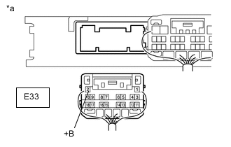
*a Rear view of wire harness connector
(to Certification ECU (smart key ECU assembly))
Disconnect the E33 certification ECU (smart key ECU assembly) connector.
-
Measure the voltage according to the value(s) in the table below.
Standard Voltage Tester Connection Condition Specified Condition E33-2 (+B) - Body ground Always 11 to 14 V Result Proceed to OK NG
NG
REPAIR OR REPLACE HARNESS OR CONNECTOR IN CIRCUIT CONNECTED TO POWER SOURCE
OK
-
-
CHECK HARNESS AND CONNECTOR (GROUND)
Result Proceed to OK NG
-
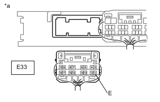
*a Rear view of wire harness connector
(to Certification ECU (smart key ECU assembly))
Measure the resistance according to the value(s) in the table below.
Standard Resistance Tester Connection Condition Specified Condition E33-11 (E) - Body ground Always Below 1 Ω Result Proceed to OK NG
NG
REPAIR OR REPLACE HARNESS OR CONNECTOR
OK
-
-
CHECK HARNESS AND CONNECTOR (CERTIFICATION ECU (SMART KEY ECU ASSEMBLY) - COMBINATION METER ASSEMBLY)
-
Disconnect the E35 certification ECU (smart key ECU assembly) connector.
-
Disconnect the E46 combination meter assembly connector.
-
Measure the resistance according to the value(s) in the table below.
Standard Resistance Tester Connection Condition Specified Condition E35-27 (SPD) - E46-6 (+S) Always Below 1 Ω E35-27 (SPD) or E46-6 (+S) - Body ground Always 10 kΩ or higher Result Proceed to OK NG
NG 
CHECK HARNESS AND CONNECTOR (COMBINATION METER ASSEMBLY - INSTRUMENT PANEL JUNCTION BLOCK ASSEMBLY) Click here
OK
-
-
CHECK CERTIFICATION ECU (SMART KEY ECU ASSEMBLY)
-
Reconnect the E35 certification ECU (smart key ECU assembly) connector.
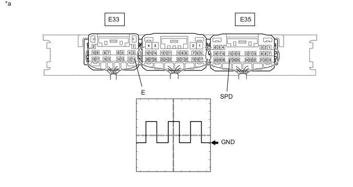
*a Component with harness connected
(Certification ECU (Smart Key ECU Assembly))
- - -
Reconnect the E46 combination meter assembly connector.
-
Using an oscilloscope, check the waveform.
-
Check the signal waveform according to the condition(s) in the table below.
Item Condition Tester Connection E35-27 (SPD) - E33-11 (E) Tool setting 5 V/DIV., 20 ms./DIV. Vehicle condition Engine switch on (IG), vehicle being driven at approx. 5 km/h (3 mph) OK The waveform is similar to that shown in the illustration. Tech Tips
When the system is functioning normally, one wheel revolution generates 4 pulses. As the vehicle speed increases, the width indicated by (A) in the illustration narrows.
Result Proceed to OK NG
OK
REPLACE CERTIFICATION ECU (SMART KEY ECU ASSEMBLY)
NG
GO TO METER / GAUGE SYSTEM (Speed Signal Circuit) Click here
-
-
CHECK HARNESS AND CONNECTOR (COMBINATION METER ASSEMBLY - INSTRUMENT PANEL JUNCTION BLOCK ASSEMBLY)
-
Disconnect the 3D instrument panel junction block assembly connector.
-
Measure the resistance according to the value(s) in the table below.
Standard Resistance Tester Connection Condition Specified Condition E46-6 (+S) - 3D-38 Always Below 1 Ω E46-6 (+S) or 3D-38 - Body ground Always 10 kΩ or higher Result Proceed to OK NG
NG
REPAIR OR REPLACE HARNESS OR CONNECTOR
OK
-
-
CHECK HARNESS AND CONNECTOR (CERTIFICATION ECU (SMART KEY ECU ASSEMBLY) - JUNCTION CONNECTOR)
-
Disconnect the E54 junction connector.
-
Measure the resistance according to the value(s) in the table below.
Standard Resistance Tester Connection Condition Specified Condition E35-27 (SPD) - E54-9 Always Below 1 Ω E35-27 (SPD) or E54-9 - Body ground Always 10 kΩ or higher Result Proceed to OK NG
NG
REPAIR OR REPLACE HARNESS OR CONNECTOR
OK
-
-
CHECK HARNESS AND CONNECTOR (INSTRUMENT PANEL JUNCTION BLOCK ASSEMBLY - JUNCTION CONNECTOR)
-
Measure the resistance according to the value(s) in the table below.
Standard Resistance Tester Connection Condition Specified Condition 3D-20 - E54-7 Always Below 1 Ω 3D-20 or E54-7 - Body ground Always 10 kΩ or higher Result Proceed to OK NG
NG
REPAIR OR REPLACE HARNESS OR CONNECTOR
OK
-
-
CHECK INSTRUMENT PANEL JUNCTION BLOCK ASSEMBLY
-
Remove the instrument panel junction block assembly.
for LHD: Click here
for RHD: Click here
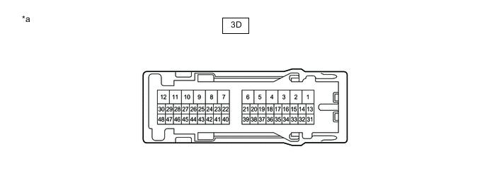
*a Component without harness connected
(Instrument Panel Junction Block Assembly)
- - -
Remove the main body ECU (multiplex network body ECU) from the instrument panel junction block assembly.
for LHD: Click here
for RHD: Click here
-
Measure the resistance according to the value(s) in the table below.
Standard Resistance Tester Connection Condition Specified Condition 3D-20 - 3D-38 Always Below 1 Ω Result Result Proceed to OK A NG (for LHD) B NG (for RHD) C
A
REPLACE CERTIFICATION ECU (SMART KEY ECU ASSEMBLY)
B
REPLACE INSTRUMENT PANEL JUNCTION BLOCK ASSEMBLY Click here
C
REPLACE INSTRUMENT PANEL JUNCTION BLOCK ASSEMBLY Click here
-