SIMPLE INTELLIGENT PARKING ASSIST SYSTEM Reverse Signal Circuit
DESCRIPTION
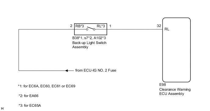
The clearance warning ECU assembly receives a reverse signal from the back-up light switch assembly. (for MT or MMT)
WIRING DIAGRAM
PROCEDURE
-
CHECK HARNESS AND CONNECTOR (REVERSE SIGNAL)
-
Disconnect the E98 clearance warning ECU assembly connector.
-
Measure the voltage according to the value(s) in the table below.
Standard Voltage Tester Connection Condition Specified Condition E98-32 (RL) - Body ground Ignition switch ON, shift lever in R 11 to 14 V Ignition switch ON, shift lever in any position other than R Below 1 V Result Proceed to OK NG
OK 
PROCEED TO NEXT SUSPECTED AREA SHOWN IN PROBLEM SYMPTOMS TABLE Click here
NG 
-
-
CHECK HARNESS AND CONNECTOR (BACK-UP LIGHT SWITCH ASSEMBLY - CLEARANCE WARNING ECU ASSEMBLY)
-
Disconnect the E98 clearance warning ECU assembly connector.
-
Disconnect the B38*1, s7*2 or A102*3 back-up light switch assembly connector.
-
*1: for EC6A, EC60, EC61 or EC69
-
*2: for EA66
-
*3: for EC65A
-
-
Measure the resistance according to the value(s) in the table below.
Standard Resistance Tester Connection Condition Specified Condition E98-32 (RL) - B38-1*1 Always Below 1 Ω E98-32 (RL) - s7-1*2 Always Below 1 Ω E98-32 (RL) - A102-1 (RL)*3 Always Below 1 Ω E98-32 (RL) - Body ground Always 10 kΩ or higher
-
*1: for EC6A, EC60, EC61 or EC69
-
*2: for EA66
-
*3: for EC65A
Result Proceed to OK NG -
NG
REPAIR OR REPLACE HARNESS OR CONNECTOR
OK
-
-
CHECK HARNESS AND CONNECTOR (BACK-UP LIGHT SWITCH ASSEMBLY POWER SOURCE)
-
Disconnect the B38*1, s7*2 or A102*3 back-up light switch assembly connector.
-
*1: for EC6A, EC60, EC61 or EC69
-
*2: for EA66
-
*3: for EC65A
-
-
Measure the voltage according to the value(s) in the table below.
Standard Voltage Tester Connection Condition Specified Condition B38-2 - Body ground*1 Ignition switch ON 11 to 14 V s7-2 - Body ground*2 Ignition switch ON 11 to 14 V A102-2 (RB) - Body ground*3 Ignition switch ON 11 to 14 V
-
*1: for EC6A, EC60, EC61 or EC69
-
*2: for EA66
-
*3: for EC65A
Result Proceed to OK NG -
OK
REPLACE BACK-UP LIGHT SWITCH ASSEMBLY for EC60: Click here
REPLACE BACK-UP LIGHT SWITCH ASSEMBLY for EC61: Click here
REPLACE BACK-UP LIGHT SWITCH ASSEMBLY for EC65A: Click here
REPLACE BACK-UP LIGHT SWITCH ASSEMBLY for EA66: Click here
REPLACE BACK-UP LIGHT SWITCH ASSEMBLY for EC69: Click here
REPLACE BACK-UP LIGHT SWITCH ASSEMBLY for EC6A: Click hereNG
REPAIR OR REPLACE HARNESS OR CONNECTOR
-