TOYOTA PARKING ASSIST-SENSOR SYSTEM(for Sedan without Simple Intelligent Parking Assist System) Clearance Warning Buzzer Circuit
DESCRIPTION
This circuit consists of the No. 1 clearance warning buzzer, No. 2 clearance warning buzzer and clearance warning ECU assembly. An ECU-excited type buzzer is used. The ECU operates the buzzers using a sound pattern that changes depending on the distance to the obstacle.
WIRING DIAGRAM
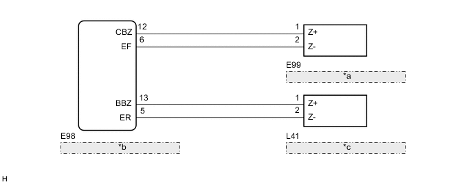
| *a | No. 1 Clearance Warning Buzzer |
| *b | Clearance Warning ECU Assembly |
| *c | No. 2 Clearance Warning Buzzer |
PROCEDURE
-
CHECK CLEARANCE WARNING BUZZER
-
Check the operation of the No. 1 and No. 2 clearance warning buzzers.
Result Result Proceed to Buzzer does not sound when an obstacle is detected in front or at the rear of the vehicle. A Buzzer does not sound only when an obstacle is detected in front of the vehicle. B Buzzer does not sound only when an obstacle is detected at the rear of the vehicle. C
A 
PROCEED TO NEXT SUSPECTED AREA SHOWN IN PROBLEM SYMPTOMS TABLE Click here
C 
PERFORM ACTIVE TEST USING GTS Click here
B 
-
-
PERFORM ACTIVE TEST USING GTS
-
Connect the GTS to the DLC3.
-
Turn the ignition switch to ON.
-
Turn the GTS on.
-
Enter the following menus: Body Electrical / Clearance Sonar/Simple-IPA. / Active Test.
-
Check that the front buzzer operates by performing the Active Test.
Body Electrical > Clearance Sonar / Simple-IPA. > Active TestTester Display Measurement Item Control Range Diagnostic Note Front Buzzer No. 1 clearance warning buzzer Stop or Operate Confirm that the vehicle is stopped and the ignition switch is ON
Body Electrical > Clearance Sonar / Simple-IPA. > Active TestTester Display Front Buzzer OK The No. 1 clearance warning buzzer sounds. Result Proceed to OK NG
OK
PROCEED TO NEXT SUSPECTED AREA SHOWN IN PROBLEM SYMPTOMS TABLE Click here
NG
-
-
CHECK HARNESS AND CONNECTOR (CLEARANCE WARNING ECU ASSEMBLY - NO. 1 CLEARANCE WARNING BUZZER)
-
Disconnect the E98 clearance warning ECU assembly connector.
-
Disconnect the E99 No. 1 clearance warning buzzer connector.
-
Measure the resistance according to the value(s) in the table below.
Standard Resistance Tester Connection Condition Specified Condition E98-12 (CBZ) - E99-1 (Z+) Always Below 1 Ω E98-6 (EF) - E99-2 (Z-) Always Below 1 Ω E98-12 (CBZ) - Body ground Always 10 kΩ or higher E98-6 (EF) - Body ground Always 10 kΩ or higher Result Proceed to OK NG
NG
REPAIR OR REPLACE HARNESS OR CONNECTOR
OK
-
-
REPLACE NO. 1 CLEARANCE WARNING BUZZER
-
Replace the No. 1 clearance warning buzzer with a new or known good one.
Result Proceed to NEXT
NEXT
-
-
PERFORM ACTIVE TEST USING GTS
-
Connect the GTS to the DLC3.
-
Turn the ignition switch to ON.
-
Turn the GTS on.
-
Enter the following menus: Body Electrical / Clearance Sonar/Simple-IPA. / Active Test.
-
Check that the front buzzer operates by performing the Active Test.
Body Electrical > Clearance Sonar / Simple-IPA. > Active TestTester Display Measurement Item Control Range Diagnostic Note Front Buzzer No. 1 clearance warning buzzer Stop or Operate Confirm that the vehicle is stopped and the ignition switch is ON
Body Electrical > Clearance Sonar / Simple-IPA. > Active TestTester Display Front Buzzer OK The No. 1 clearance warning buzzer sounds. Result Result Proceed to OK A NG B
A
END (NO. 1 CLEARANCE WARNING BUZZER WAS DEFECTIVE)
B
REPLACE CLEARANCE WARNING ECU ASSEMBLY Click here
-
-
PERFORM ACTIVE TEST USING GTS
-
Connect the GTS to the DLC3.
-
Turn the ignition switch to ON.
-
Turn the GTS on.
-
Enter the following menus: Body Electrical / Clearance Sonar/Simple-IPA. / Active Test.
-
Check that the rear buzzer operates by performing the Active Test.
Body Electrical > Clearance Sonar / Simple-IPA. > Active TestTester Display Measurement Item Control Range Diagnostic Note Rear Buzzer No. 2 clearance warning buzzer Stop or Operate Confirm that the vehicle is stopped and the ignition switch is ON
Body Electrical > Clearance Sonar / Simple-IPA. > Active TestTester Display Rear Buzzer OK The No. 2 clearance warning buzzer sounds. Result Proceed to OK NG
OK
PROCEED TO NEXT SUSPECTED AREA SHOWN IN PROBLEM SYMPTOMS TABLE Click here
NG
-
-
CHECK HARNESS AND CONNECTOR (CLEARANCE WARNING ECU ASSEMBLY - NO. 2 CLEARANCE WARNING BUZZER)
-
Disconnect the E98 clearance warning ECU assembly connector.
-
Disconnect the L41 No. 2 clearance warning buzzer connector.
-
Measure the resistance according to the value(s) in the table below.
Standard Resistance Tester Connection Condition Specified Condition E98-13 (BBZ) - L41-1 (Z+) Always Below 1 Ω E98-5 (ER) - L41-2 (Z-) Always Below 1 Ω E98-13 (BBZ) - Body ground Always 10 kΩ or higher E98-5 (ER) - Body ground Always 10 kΩ or higher Result Proceed to OK NG
NG
REPAIR OR REPLACE HARNESS OR CONNECTOR
OK
-
-
REPLACE NO. 2 CLEARANCE WARNING BUZZER
-
Replace the No. 2 clearance warning buzzer with a new or known good one.
Result Proceed to NEXT
NEXT
-
-
PERFORM ACTIVE TEST USING GTS
-
Connect the GTS to the DLC3.
-
Turn the ignition switch to ON.
-
Turn the GTS on.
-
Enter the following menus: Body Electrical / Clearance Sonar/Simple-IPA. / Active Test.
-
Check that the rear buzzer operates by performing the Active Test.
Body Electrical > Clearance Sonar / Simple-IPA. > Active TestTester Display Measurement Item Control Range Diagnostic Note Rear Buzzer No. 2 clearance warning buzzer Stop or Operate Confirm that the vehicle is stopped and the ignition switch is ON
Body Electrical > Clearance Sonar / Simple-IPA. > Active TestTester Display Rear Buzzer OK The No. 2 clearance warning buzzer sounds. Result Result Proceed to OK A NG B
A
END (NO. 2 CLEARANCE WARNING BUZZER WAS DEFECTIVE)
B
REPLACE CLEARANCE WARNING ECU ASSEMBLY Click here
-