TOYOTA PARKING ASSIST-SENSOR SYSTEM(except Hatchback) OPERATION CHECK
-
MALFUNCTION DISPLAY (MULTI-INFORMATION DISPLAY)
-
Open circuit indication
-
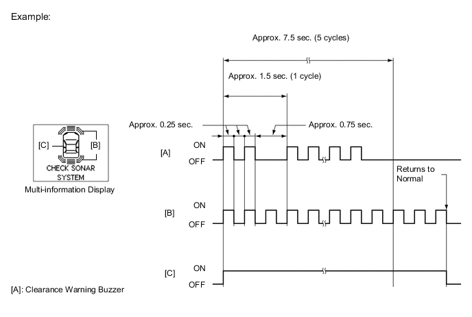
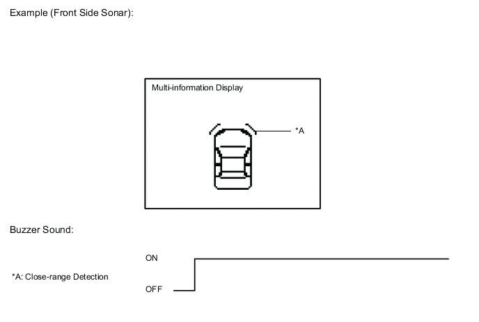
If there is an open circuit between the ultrasonic sensor and the clearance warning ECU assembly or a sensor is malfunctioning, the malfunction is displayed as shown in the illustration.
Tech Tips
-
When a malfunction is detected, bars for all detection areas shown in the illustration blink.
-
If a sensor has an open circuit, check for DTCs and troubleshoot according to each inspection procedure.
-
-
-
-
DETECTION RANGE MEASUREMENT AND DISPLAY INSPECTION
Note
While performing the following measurement and inspection, make sure to depress the brake pedal to prevent the vehicle from moving. (The parking brake should be released.) (for EA66, EC60, EC61, EC65A, or EC69)
The following measurement and inspection will be performed with the shift lever in a position other than P. Be sure to apply the parking brake and depress the brake pedal firmly to prevent the vehicle from moving. (for K311)
-
Turn the ignition switch to ON.
-
Turn the back sonar or clearance sonar switch assembly on.
-
Detection range measurement:
-
When measuring the detection range of the front sonar, move the shift lever to any position other than P. (for K311)
-
When measuring the detection range of the rear sonar, move the shift lever to R.
-
Move a 60 mm (2.36 in.) diameter pole near each sensor to measure its detection range. (for Wagon)
Note
These detection ranges are applicable when positioning the 60 mm (2.36 in.) diameter pole parallel or perpendicular to the ground. The detection range varies depending on the measuring method and type of obstacle (such as walls).
Tech Tips
Have an assistant move the pole.
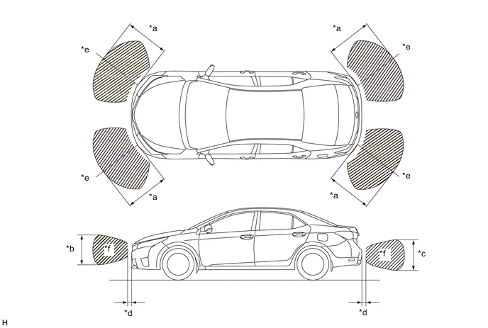
Figure 1. Corner Sonar
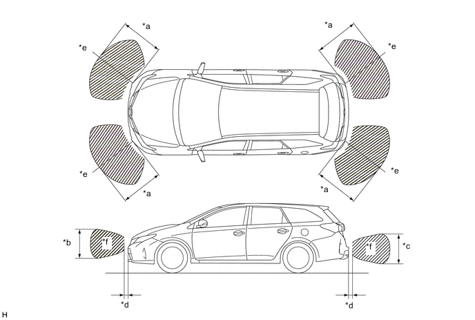
*a Approx. 500 mm (19.7 in.) *b Approx. 650 mm (25.6 in.) *c Approx. 550 mm (21.7 in.) *d Approx. 100 mm (3.9 in.) *e A *f B Note
The ultrasonic sensor side view detection range (hatched area labeled (B)) represents the cross section of the top view detection range (A). The hatched area (A) does not represent the entire side view detection range.
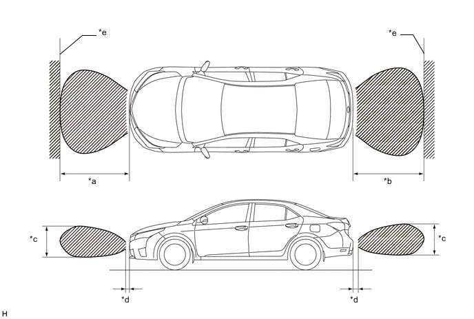
Figure 2. Center Sonar
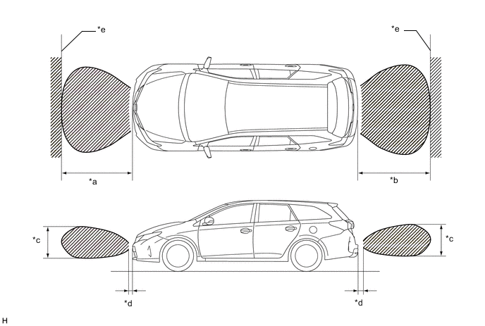
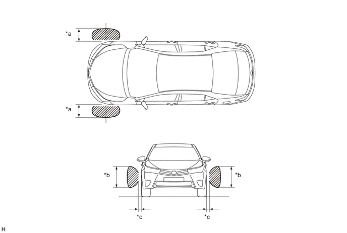
*a Approx. 1000 mm (39.4 in.) *b Approx. 1500 mm (59.1 in.) *c Approx. 650 mm (25.6 in.) *d Approx. 100 mm (3.9 in.) *e Wall - - Figure 3. Front Side Sonar
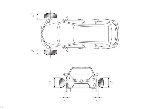
*a Approx. 250 mm (9.8 in.) *b Approx. 400 mm (15.7 in.) *c Approx. 100 mm (3.9 in.) - - -
Move a 60 mm (2.36 in.) diameter pole near each sensor to measure its detection range. (for Sedan)
Note
These detection ranges are applicable when positioning the 60 mm (2.36 in.) diameter pole parallel or perpendicular to the ground. The detection range varies depending on the measuring method and type of obstacle (such as walls).
Tech Tips
Have an assistant move the pole.
Figure 4. Corner Sonar
*a Approx. 500 mm (19.7 in.) *b Approx. 650 mm (25.6 in.) *c Approx. 550 mm (21.7 in.) *d Approx. 100 mm (3.9 in.) *e A *f B Note
The ultrasonic sensor side view detection range (hatched area labeled (B)) represents the cross section of the top view detection range (A). The hatched area (A) does not represent the entire side view detection range.
Figure 5. Center Sonar
*a Approx. 1000 mm (39.4 in.) *b Approx. 1500 mm (59.1 in.) *c Approx. 650 mm (25.6 in.) *d Approx. 100 mm (3.9 in.) *e Wall - - Figure 6. Front Side Sonar
*a Approx. 250 mm (9.8 in.) *b Approx. 400 mm (15.7 in.) *c Approx. 100 mm (3.9 in.) - -
-
-
Front side sonar display and buzzer operation check
-
When the No. 1 ultrasonic sensors (front side LH/RH) have detected an obstacle, check the displays and check that the No. 1 clearance warning buzzer sounds. (for Wagon)
When the No. 2 ultrasonic sensors (front side LH/RH) have detected an obstacle, check the displays and check that the No. 1 clearance warning buzzer sounds. (for Sedan)
Operation Condition Ignition Switch Back Sonar or Clearance Sonar Switch Assembly Shift Lever Position Vehicle Speed Parking Brake ON On In any position other than R*1
In any position other than P or R*2
Less than 10 km/h (6 mph) Released*1 ON On R - -
-
*1: for EA66, EC60, EC61, EC65A or EC69
-
*2: for K311
Tech Tips
Ultrasonic waves are used to measure the detection range; however, the detection range may vary depending on the ambient temperature.
-
-
-
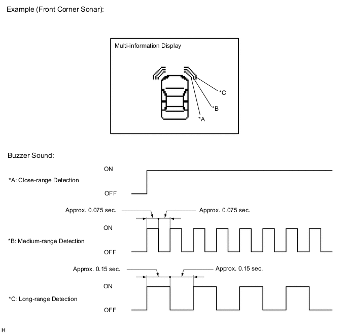
Front corner sonar display and buzzer operation check
-
When the No. 2 ultrasonic sensors (front corner LH/RH) have detected an obstacle, check the displays and check that the No. 1 clearance warning buzzer sounds. (for Wagon)
When the No. 1 ultrasonic sensors (front corner LH/RH) have detected an obstacle, check the displays and check that the No. 1 clearance warning buzzer sounds. (for Sedan)
Operation Condition Ignition Switch Back Sonar or Clearance Sonar Switch Assembly Shift Lever Position Vehicle Speed Parking Brake ON On In any position other than R*1
In any position other than P or R*2
Less than 10 km/h (6 mph) Released*1 ON On R - -
-
*1: for EA66, EC60, EC61, EC65A or EC69
-
*2: for K311
Tech Tips
Ultrasonic waves are used to measure the detection range; however, the detection range may vary depending on the ambient temperature.
-
-
-
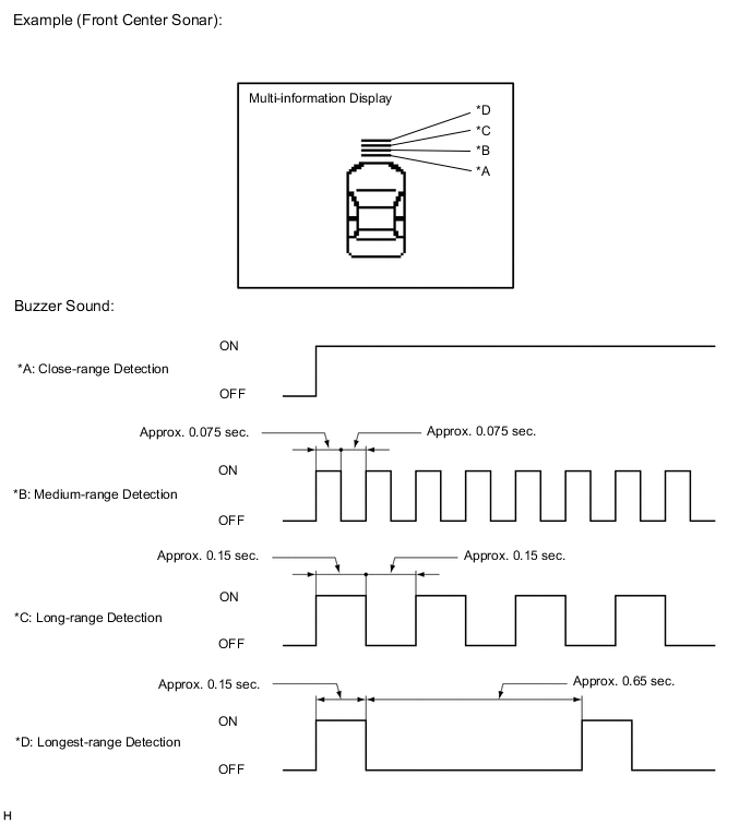
Front center sonar display and buzzer operation check
-
When the No. 2 ultrasonic sensors (front center LH/RH) have detected an obstacle, check the display and check that the No. 1 clearance warning buzzer sounds. (for Wagon)
When the No. 1 ultrasonic sensors (front center LH/RH) have detected an obstacle, check the display and check that the No. 1 clearance warning buzzer sounds. (for Sedan)
Operation Condition Ignition Switch Back Sonar or Clearance Sonar Switch Assembly Shift Lever Position Vehicle Speed Parking Brake ON On In any position other than R*1
In any position other than P or R*2
Less than 10 km/h (6 mph) Released*1 ON On R - -
-
*1: for EA66, EC60, EC61, EC65A or EC69
-
*2: for K311
Tech Tips
Ultrasonic waves are used to measure the detection range; however, the detection range may vary depending on the ambient temperature.
-
*1: While the simple intelligent parking assist system is not operating
-
*2: While the simple intelligent parking assist system is operating
-
-
-
Rear corner sonar display and buzzer operation check
-
When the No. 4 ultrasonic sensors (rear corner LH/RH) have detected an obstacle, check the display and check that the No. 2 clearance warning buzzer sounds. (for Wagon)
When the No. 3 ultrasonic sensors (rear corner LH/RH) have detected an obstacle, check the display and check that the No. 2 clearance warning buzzer sounds. (for Sedan)
Operation Condition Ignition Switch Back Sonar or Clearance Sonar Switch Assembly Shift Lever Position Vehicle Speed Parking Brake ON On R - - 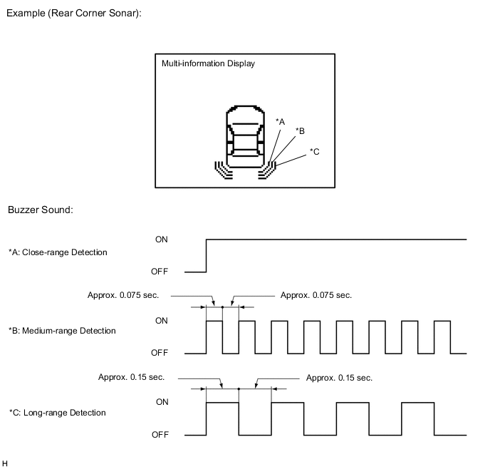
Tech Tips
Ultrasonic waves are used to measure the detection range; however, the detection range may vary depending on the ambient temperature.
-
-
Rear center sonar display and buzzer operation check
-
When the No. 4 ultrasonic sensors (rear center LH/RH) have detected an obstacle, check the display and check that the No. 2 clearance warning buzzer sounds. (for Wagon)
When the No. 3 ultrasonic sensors (rear center LH/RH) have detected an obstacle, check the display and check that the No. 2 clearance warning buzzer sounds. (for Sedan)
Operation Condition Ignition Switch Back Sonar or Clearance Sonar Switch Assembly Shift Lever Position Vehicle Speed Parking Brake ON On R - - 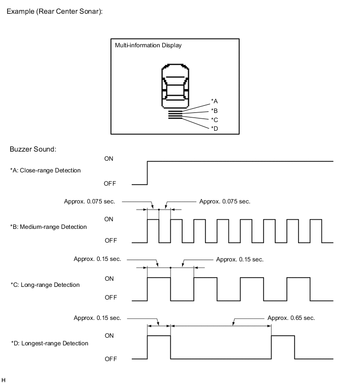
Tech Tips
Ultrasonic waves are used to measure the detection range; however, the detection range may vary depending on the ambient temperature.
-
*1: While the simple intelligent parking assist system is not operating
-
*2: While the simple intelligent parking assist system is operating
-
-
-