TOYOTA PARKING ASSIST-SENSOR SYSTEM(except Hatchback) Clearance Sonar Main Switch Circuit
DESCRIPTION
The back sonar or clearance sonar switch assembly is installed at the base of the driver side of the instrument panel.
When the back sonar or clearance sonar switch assembly is turned on, an on signal is sent to the clearance warning ECU assembly. The Toyota parking assist-sensor system operates according to this signal.
WIRING DIAGRAM
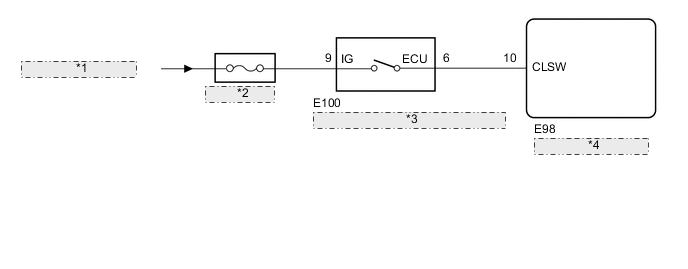
| *1 | from IG1 NO. 3 Relay |
| *2 | ECU-IG NO. 4 |
| *3 | Back Sonar or Clearance Sonar Switch Assembly |
| *4 | Clearance Warning ECU Assembly |
CAUTION / NOTICE / HINT
Note
-
Inspect the fuses for circuits related to this system before performing the following procedure.
-
Depending on the parts that are replaced during vehicle inspection or maintenance, performing initialization may be needed. Refer to Initialization.
PROCEDURE
-
INSPECT BACK SONAR OR CLEARANCE SONAR SWITCH ASSEMBLY
-
Remove the back sonar or clearance sonar switch assembly.
for Wagon: Click here
for Sedan: Click here
-
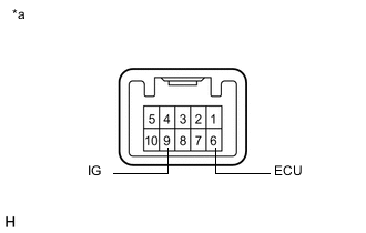
*a Component without harness connected
(Back Sonar or Clearance Sonar Switch Assembly)
Measure the resistance according to the value(s) in the table below.
Standard Resistance Tester Connection Condition Specified Condition 9 (IG) - 6 (ECU) Back sonar or clearance sonar switch assembly on Below 1 Ω 9 (IG) - 6 (ECU) Back sonar or clearance sonar switch assembly off 10 kΩ or higher Result Proceed to OK NG
NG 
REPLACE BACK SONAR OR CLEARANCE SONAR SWITCH ASSEMBLY for Wagon: Click here
REPLACE BACK SONAR OR CLEARANCE SONAR SWITCH ASSEMBLY for Sedan: Click hereOK 
-
-
CHECK HARNESS AND CONNECTOR (BACK SONAR OR CLEARANCE SONAR SWITCH ASSEMBLY POWER SOURCE)
-
Measure the voltage according to the value(s) in the table below.
Standard Voltage Tester Connection Condition Specified Condition E100-9 (IG) - Body ground Ignition switch ON 11 to 14 V E100-9 (IG) - Body ground Ignition switch off Below 1 V Result Proceed to OK NG
NG
REPAIR OR REPLACE HARNESS OR CONNECTOR
OK
-
-
CHECK HARNESS AND CONNECTOR (BACK SONAR OR CLEARANCE SONAR SWITCH ASSEMBLY - CLEARANCE WARNING ECU ASSEMBLY)
-
Disconnect the E98 clearance warning ECU assembly connector.
-
Measure the resistance according to the value(s) in the table below.
Standard Resistance Tester Connection Condition Specified Condition E98-10 (CLSW) - E100-6 (ECU) Always Below 1 Ω E98-10 (CLSW) - Body ground Always 10 kΩ or higher Result Result Proceed to OK A NG B
A
REPLACE CLEARANCE WARNING ECU ASSEMBLY for Wagon LHD: Click here
REPLACE CLEARANCE WARNING ECU ASSEMBLY for Wagon RHD: Click here
REPLACE CLEARANCE WARNING ECU ASSEMBLY for Sedan: Click hereB
REPAIR OR REPLACE HARNESS OR CONNECTOR
-