NAVIGATION SYSTEM Illumination Circuit
DESCRIPTION
Power is supplied to the radio and display receiver assembly and steering pad switch assembly illumination when the light control switch is in the tail or head position.
WIRING DIAGRAM
Figure 1. for Sedan
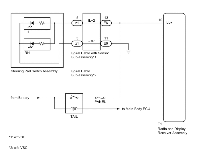
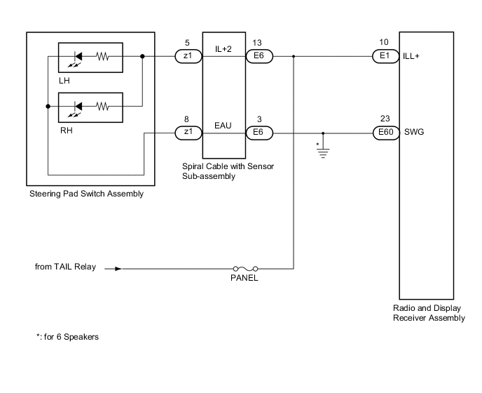
Figure 2. for Hatchback, Wagon
CAUTION / NOTICE / HINT
Note
-
The vehicle is equipped with a Supplemental Restraint System (SRS) which includes components such as airbags. Before servicing (including removal or installation of parts), be sure to read the precaution for Supplemental Restraint System.
-
Inspect the fuses for circuits related to this system before performing the following procedure.
PROCEDURE
-
CHECK ILLUMINATION
-
Check if the illumination for the radio and display receiver assembly, steering pad switch assembly, heater control switch or others (hazard switch, transmission control switch, etc.) comes on when the light control switch is turned to the head or tail position.
Result Result Proceed to Illumination comes on for all components except steering pad switch assembly. A Illumination comes on for all components except radio and display receiver assembly. B No illumination comes on (radio and display receiver assembly, hazard switch, heater control switch, etc.). C
B 
CHECK HARNESS AND CONNECTOR (ILLUMINATION SIGNAL) Click here
C 
GO TO LIGHTING SYSTEM Click here
A 
-
-
CHECK HARNESS AND CONNECTOR (ILLUMINATION SIGNAL)
-
Disconnect the E6 spiral cable with sensor sub-assembly connector (w/ VSC).
Disconnect the E6 spiral cable sub-assembly connector (w/o VSC).
-
Measure the voltage according to the value(s) in the table below.
Standard Voltage Tester Connection Condition Specified Condition E6-13 (IL+2) - Body ground Light control switch in the tail or head position 11 to 14 V Result Proceed to OK NG
NG
REPAIR OR REPLACE HARNESS OR CONNECTOR
OK
-
-
INSPECT STEERING PAD SWITCH ASSEMBLY
-
Remove the steering pad switch assembly.
-
Connect a positive (+) lead from the battery to terminal 5 (IL+2) and a negative (-) lead to terminal 3 (-DP) of the steering pad switch assembly connector.(for Sedan)
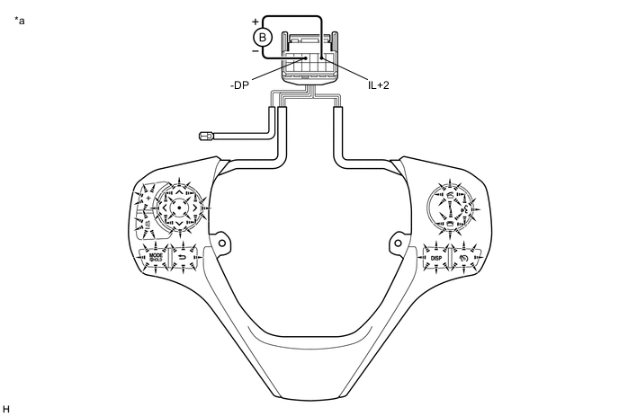
*a Component without harness connected
(Steering Pad Switch Assembly)
- - -
Connect a positive (+) lead from the battery to terminal 5 (IL+2) and a negative (-) lead to terminal 8 (EAU) of the steering pad switch assembly connector.(for Hatchback, Wagon)
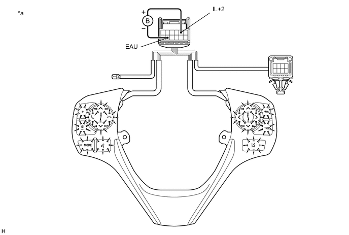
*a Component without harness connected
(Steering Pad Switch Assembly)
- - -
Check if the illumination for the steering pad switch assembly comes on.
OK Illumination for the steering pad switch assembly comes on. Result Result Proceed to OK (w/ VSC) A OK (w/o VSC) B NG C
B
INSPECT SPIRAL CABLE SUB-ASSEMBLY Click here
C
REPLACE STEERING PAD SWITCH ASSEMBLY Click here
A
-
-
INSPECT SPIRAL CABLE WITH SENSOR SUB-ASSEMBLY
-
Remove the spiral cable with sensor sub-assembly.
-
Figure 3. for Sedan

*a Component without harness connected
(Spiral Cable with Sensor Sub-assembly)
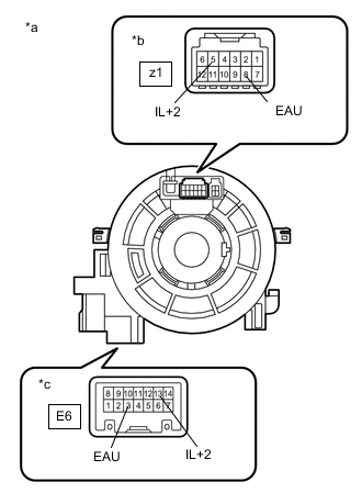
*b Steering Pad Switch Assembly Side *c Vehicle Side Figure 4. for Hatchback, Wagon
*a Component without harness connected
(Spiral Cable with Sensor Sub-assembly)
*b Steering pad switch assembly side *c Vehicle side Measure the resistance according to the value(s) in the table below.
Standard Resistance for Sedan Tester Connection Condition Specified Condition z1-5 (IL+2) - E6-13 (IL+2) Center 3 Ω or less 2.5 rotations to the left 2.5 rotations to the right z1-3 (-DP) - E6-11 (-DP) Center 3 Ω or less 2.5 rotations to the left 2.5 rotations to the right for Hatchback, Wagon Tester Connection Condition Specified Condition z1-5 (IL+2) - E6-13 (IL+2) Center 3 Ω or less 2.5 rotations to the left 2.5 rotations to the right z1-8 (EAU) - E6-3 (EAU) Center 3 Ω or less 2.5 rotations to the left 2.5 rotations to the right -
After setting the spiral cable with sensor sub-assembly to the center position, rotate the spiral cable with sensor sub-assembly 2.5 times clockwise. Then while rotating the spiral cable with sensor sub-assembly 5 times counterclockwise, measure the resistance according to the table below.
Standard Resistance for Sedan Tester Connection Condition Specified Condition z1-5 (IL+2) - E6-13 (IL+2) Always 3 Ω or less z1-3 (-DP) - E6-11 (-DP) Always 3 Ω or less for Hatchback, Wagon Tester Connection Condition Specified Condition z1-5 (IL+2) - E6-13 (IL+2) Always 3 Ω or less z1-8 (EAU) - E6-3 (EAU) Always 3 Ω or less Note
-
Press and hold the lock located in the center of the spiral cable with sensor sub-assembly to rotate the spiral cable with sensor sub-assembly.
-
The spiral cable with sensor sub-assembly is an important part of the SRS airbag system. Incorrect removal or installation of the spiral cable with sensor sub-assembly may prevent the airbag from deploying.
-
As the spiral cable with sensor sub-assembly may break, do not rotate the spiral cable with sensor sub-assembly more than the specified amount.
Result Proceed to OK NG -
OK
REPAIR OR REPLACE HARNESS OR CONNECTOR (SPIRAL CABLE WITH SENSOR SUB-ASSEMBLY - BODY GROUND)
NG
REPLACE SPIRAL CABLE WITH SENSOR SUB-ASSEMBLY Click here
-
-
INSPECT SPIRAL CABLE SUB-ASSEMBLY
-
Remove the spiral cable sub-assembly.
-
*a Component without harness connected
(Spiral Cable Sub-assembly)
*b Steering Pad Switch Assembly Side *c Vehicle Side Measure the resistance according to the value(s) in the table below.
Standard Resistance Tester Connection Condition Specified Condition z1-5 (IL+2) - E6-13 (IL+2) Center 3 Ω or less 2.5 rotations to the left 2.5 rotations to the right z1-3 (-DP) - E6-11 (-DP) Center 3 Ω or less 2.5 rotations to the left 2.5 rotations to the right -
After setting the spiral cable sub-assembly to the center position, rotate the spiral cable sub-assembly 2.5 times clockwise. Then while rotating the spiral cable sub-assembly 5 times counterclockwise, measure the resistance according to the table below.
Standard Resistance Tester Connection Condition Specified Condition z1-5 (IL+2) - E6-13 (IL+2) Always 3 Ω or less z1-3 (-DP) - E6-11 (-DP) Always 3 Ω or less Note
-
Press and hold the lock located in the center of the spiral cable sub-assembly to rotate the spiral cable sub-assembly.
-
The spiral cable sub-assembly is an important part of the SRS airbag system. Incorrect removal or installation of the spiral cable sub-assembly may prevent the airbag from deploying.
-
As the spiral cable sub-assembly may break, do not rotate the spiral cable sub-assembly more than the specified amount.
Result Proceed to OK NG -
OK
REPAIR OR REPLACE HARNESS OR CONNECTOR (SPIRAL CABLE SUB-ASSEMBLY - BODY GROUND)
NG
REPLACE SPIRAL CABLE SUB-ASSEMBLY Click here
-
-
CHECK HARNESS AND CONNECTOR (ILLUMINATION SIGNAL)
-
Disconnect the E1 radio and display receiver assembly connector.
-
Measure the voltage according to the value(s) in the table below.
Standard Voltage Tester Connection Condition Specified Condition E1-10 (ILL+) - Body ground Light control switch in the tail or head position 11 to 14 V Result Proceed to OK NG
OK
PROCEED TO NEXT SUSPECTED AREA SHOWN IN PROBLEM SYMPTOMS TABLE Click here
NG
REPAIR OR REPLACE HARNESS OR CONNECTOR
-