AUDIO AND VISUAL SYSTEM(except Sedan Radio and Display Type), Diagnostic DTC:B158F
| DTC Code | DTC Name |
|---|---|
| B158F | AV Signal Stoppage (Low Battery Voltage) |
DESCRIPTION
This DTC is stored when a video or audio signal is interrupted due to battery voltage input to the radio and display receiver assembly dropping temporarily.
| DTC No. | Detection Item | DTC Detection Condition | Trouble Area |
|---|---|---|---|
| B158F | AV Signal Stoppage (Low Battery Voltage) | A video or audio signal is interrupted when the battery voltage drops |
|
-
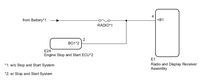
*: w/ Stop and Start System
WIRING DIAGRAM
CAUTION / NOTICE / HINT
Note
Inspect the fuses for circuits related to this system before performing the following procedure.
PROCEDURE
-
CHECK VEHICLE SIGNAL (OPERATION CHECK)
-
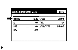
Enter the "Vehicle Signal Check Mode" screen. Refer to Check Vehicle Signal in Operation Check.
-
Measure the battery voltage.
Standard Voltage 11 to 14 V (w/o Stop and Start System) 9.5 to 14 V (w/ Stop and Start System) Tech Tips
This display is updated once per second.
Result Result Proceed to OK A NG (w/o Stop and Start System) B NG (w/ Stop and Start System) C
B 
CHECK HARNESS AND CONNECTOR (RADIO AND DISPLAY RECEIVER ASSEMBLY POWER SOURCE) Click here
C
CHECK HARNESS AND CONNECTOR (RADIO AND DISPLAY RECEIVER ASSEMBLY - ENGINE STOP AND START ECU) Click here
A 
-
-
CHECK DTC
-
Clear the DTCs.
Body Electrical > Navigation System > Clear DTCs -
Recheck for DTCs and check that no DTCs are output.
Body Electrical > Navigation System > Trouble CodesOK No DTCs are output. Result Proceed to OK NG
OK 
END
NG
REPLACE RADIO AND DISPLAY RECEIVER ASSEMBLY Click here
-
-
CHECK HARNESS AND CONNECTOR (RADIO AND DISPLAY RECEIVER ASSEMBLY POWER SOURCE)
-
Disconnect the E1 radio and display receiver assembly connector.
-
Measure the voltage according to the value(s) in the table below.
Standard Voltage Tester Connection Condition Specified Condition E1-4 (+B1) - Body ground Always 11 to 14 V Result Proceed to OK NG
OK
REPLACE RADIO AND DISPLAY RECEIVER ASSEMBLY Click here
NG
REPAIR OR REPLACE HARNESS OR CONNECTOR
-
-
CHECK HARNESS AND CONNECTOR (RADIO AND DISPLAY RECEIVER ASSEMBLY - ENGINE STOP AND START ECU)
-
Disconnect the E1 radio and display receiver assembly connector.
-
Disconnect the E24 engine stop and start ECU connector.
-
Measure the resistance according to the value(s) in the table below.
Standard Resistance Tester Connection Condition Specified Condition E1-4 (+B1) - E24-2 (BO1) Always Below 1 Ω E1-4 (+B1) - Body ground Always 10 kΩ or higher Result Proceed to OK NG
NG
REPAIR OR REPLACE HARNESS OR CONNECTOR
OK
-
-
CHECK HARNESS AND CONNECTOR (RADIO AND DISPLAY RECEIVER ASSEMBLY POWER SOURCE)
-
Disconnect the E1 radio and display receiver assembly connector.
-
Reconnect the E24 engine stop and start ECU connector.
-
Measure the voltage according to the value(s) in the table below.
Standard Voltage Tester Connection Condition Specified Condition E1-4 (+B1) - Body ground Always 9.5 to 14 V Result Proceed to OK NG
OK
REPLACE RADIO AND DISPLAY RECEIVER ASSEMBLY Click here
NG
GO TO STOP AND START SYSTEM Click here
-