AUDIO AND VISUAL SYSTEM(for Radio Receiver Type) Vehicle Speed Signal Circuit between Radio Receiver and Combination Meter
DESCRIPTION
This circuit is necessary for the Automatic Sound Levelizer (ASL) built into the radio receiver assembly.
The Automatic Sound Levelizer (ASL) function automatically adjusts the audio system volume level in order to compensate for increased vehicle noise (vehicle noise tends to increase as vehicle speed increases). The ASL adjusts the volume level based upon vehicle speed signals that it receives from the combination meter assembly.
Tech Tips
-
A voltage of 12 V or 5 V is output from each ECU and then input to the combination meter assembly. The signal is changed to a pulse signal at the transistor in the combination meter assembly. Each ECU controls its respective system based on this pulse signal.
-
If a short occurs in any of the ECUs or in the wire harness connected to an ECU, all systems in the following diagram will not operate normally.
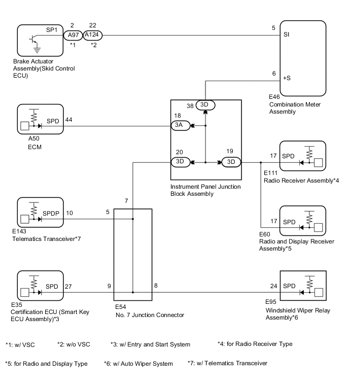
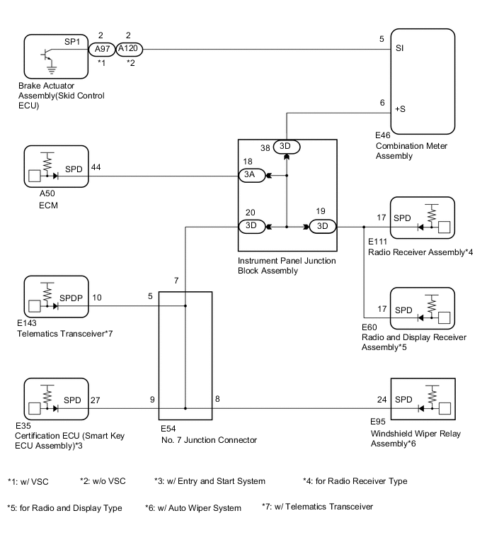
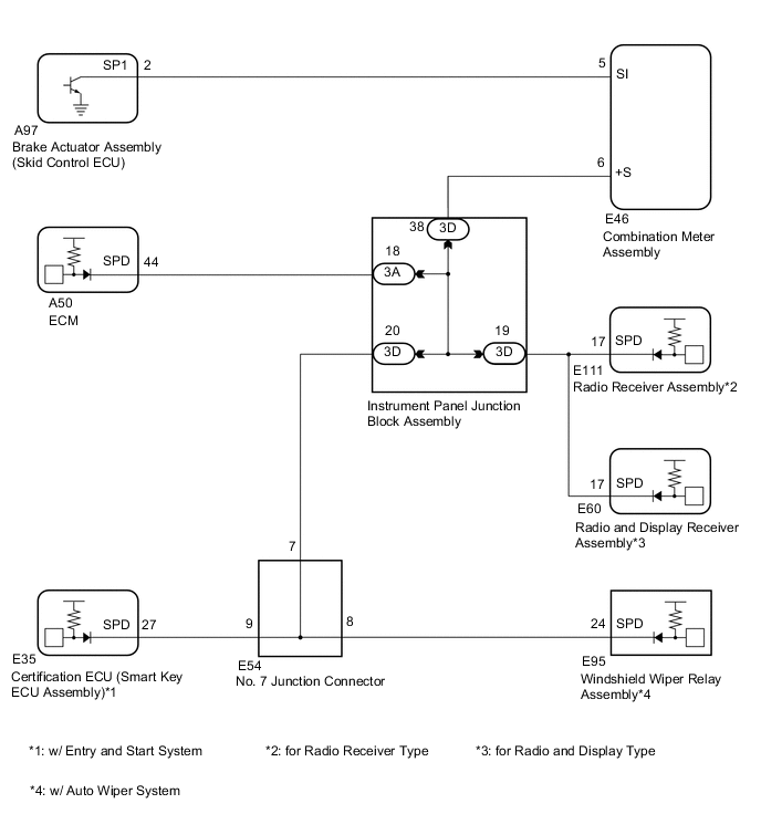
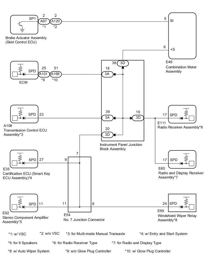
WIRING DIAGRAM
-
for 1ZR-FE, 2ZR-FE
-
for 1NR-FE
-
for 1ZR-FAE
-
for 1ND-TV
PROCEDURE
-
INSPECT COMBINATION METER ASSEMBLY (OUTPUT WAVEFORM)
-
Check the output waveform.
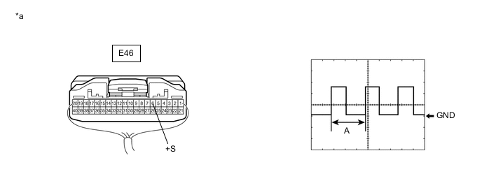
*a Component with harness connected
(Combination Meter Assembly)
- -
-
Remove the combination meter assembly with the connector still connected.
-
Connect an oscilloscope to terminal E46-6 (+S) and body ground.
-
Turn the ignition switch to ON.
-
Turn a wheel slowly.
-
Check the signal waveform according to the condition(s) in the table below.
Item Condition Measurement terminal E46-6 (+S) - Body ground Tool setting 5 V/DIV., 20 ms./DIV. Vehicle condition Wheel being rotated OK The waveform is similar to that shown in the illustration. Tech Tips
When the system is functioning normally, one wheel revolution generates 4 pulses. As the vehicle speed increases, the width indicated by (A) in the illustration narrows.
Result Proceed to OK NG -
NG 
GO TO METER / GAUGE / DISPLAY Click here
OK 
-
-
INSPECT RADIO RECEIVER ASSEMBLY (INPUT WAVEFORM)
-
Check the output waveform.
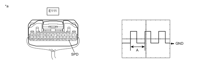
*a Component with harness connected
(Radio Receiver Assembly)
- -
-
Remove the combination meter assembly with the connector still connected.
-
Connect an oscilloscope to terminal E111-17 (SPD) and body ground.
-
Turn the ignition switch to ON.
-
Turn a wheel slowly.
-
Check the signal waveform according to the condition(s) in the table below.
Item Condition Measurement terminal E111-17 (SPD) - Body ground Tool setting 5 V/DIV., 20 ms./DIV. Vehicle condition Wheel being rotated OK The waveform is similar to that shown in the illustration. Tech Tips
When the system is functioning normally, one wheel revolution generates 4 pulses. As the vehicle speed increases, the width indicated by (A) in the illustration narrows.
Result Proceed to OK NG -
OK
REPLACE RADIO RECEIVER ASSEMBLY for Sedan: Click here
REPLACE RADIO RECEIVER ASSEMBLY for Hatchback, Wagon: Click hereNG
-
-
CHECK HARNESS AND CONNECTOR (RADIO RECEIVER ASSEMBLY - INSTRUMENT PANEL JUNCTION BLOCK ASSEMBLY)
-
Disconnect the E111 radio receiver assembly connector.
-
Disconnect the 3D instrument panel junction block assembly.
-
Measure the resistance according to the value(s) in the table below.
Standard Resistance Tester Connection Condition Specified Condition E111-17 (SPD) - 3D-19 Always Below 1 Ω Result Proceed to OK NG
NG
REPAIR OR REPLACE HARNESS OR CONNECTOR
OK
-
-
INSPECT INSTRUMENT PANEL JUNCTION BLOCK ASSEMBLY
-
Remove the instrument panel junction block assembly.
-
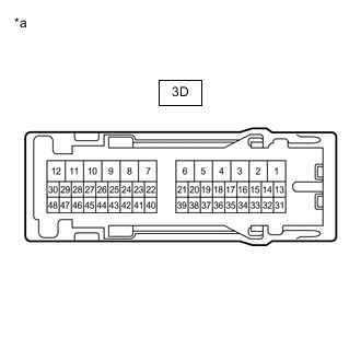
*a Component without harness connected
(Instrument Panel Junction Block Assembly)
Measure the resistance according to the value(s) in the table below.
Standard Resistance Tester Connection Condition Specified Condition 3D-19 - 3D-38 Always Below 1 Ω Result Proceed to OK NG
OK
REPAIR OR REPLACE HARNESS OR CONNECTOR (INSTRUMENT PANEL JUNCTION BLOCK ASSEMBLY - COMBINATION METER ASSEMBLY)
NG
REPLACE INSTRUMENT PANEL JUNCTION BLOCK ASSEMBLY for LHD: Click here
REPLACE INSTRUMENT PANEL JUNCTION BLOCK ASSEMBLY for RHD: Click here -