STEERING COLUMN ASSEMBLY REASSEMBLY

PROCEDURE
-
INSTALL POWER STEERING ECU WITH MOTOR ASSEMBLY
Note
-
Do not drop the power steering ECU with motor assembly, strike it with tools or subject it to impacts.
-
If the power steering ECU with motor assembly is subjected to an impact, replace it with a new one.
-
Do not pull the wire harness of the power steering ECU with motor assembly.
-
Do not allow any moisture to come into contact with the power steering ECU with motor assembly.
-
Do not loosen any bolts not mentioned in the procedure.
-
Do not allow any foreign matter to contaminate the power steering ECU with motor assembly.
-
Install a new electric power steering motor shaft damper to the electric power steering column sub-assembly.
-
Install a new electric power steering motor shaft spacer to the electric power steering column sub-assembly.
-
Using a T40 "TORX" socket wrench, temporarily install the power steering ECU with motor assembly and bracket to the electric power steering column sub-assembly with the 2 bolts.
Note
When temporarily installing the 2 bolts to the power steering ECU with motor assembly, do not tighten them all the way down.
Tech Tips
If the bolts are to be replaced with new ones, hexagon bolts will be provided.
-
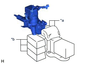
*a Cloth *b Wooden Block Secure the steering column assembly in a vise using aluminum plates, cloths and wooden blocks.
Note
-
Do not overtighten the vise, as the steering column assembly may become deformed.
-
Secure the power steering ECU with motor assembly so that it is upright.
-
Support the steering column assembly with wooden blocks or similar items to ensure that it does not fall.
-
-

Using SST, turn the steering main shaft once 180 degrees to the left and then 180 degrees to the right at a speed of 60 rpm, and repeat 2 to 3 times to adjust the axis centering of the power steering ECU with motor assembly.
- SST
- 09616-00011
-
Using a T40 "TORX" socket wrench, tighten the 2 bolts.
- Torque:
- 18.5 N*m { 189 kgf*cm, 14 ft.*lbf }
Tech Tips
If the bolts are to be replaced with new ones, hexagon bolts will be provided.
-
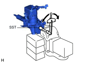
Using SST and a torque wrench, measure the turning torque of the steering main shaft.
- SST
- 09616-00011
Torque Turning torque 0.9 to 1.5 N*m (10 to 15 kgf*cm , 8 to 13 in.*lbf) Note
Ensure that there is no abnormal resistance during rotation.
If the turning torque is not as specified, readjust the axis centering of the power steering ECU with motor assembly.
-
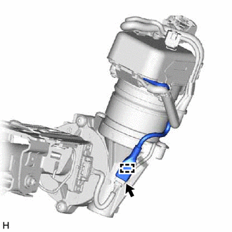
Connect the connector.
-
Engage the wire harness clamp.
-
When replacing the power steering ECU with motor assembly (for LHD):
-
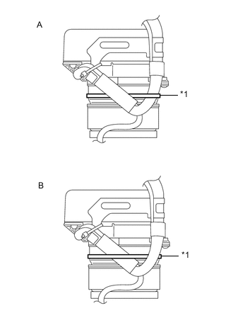
*1 Clamp Install a new clamp to the power steering ECU with motor assembly as shown in the illustration.
Tech Tips
The clamp can be installed either way indicated by A or B.
-
-
When replacing the power steering ECU with motor assembly (for RHD):
-
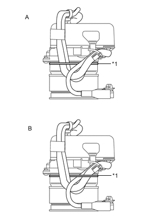
*1 Clamp Install a new clamp to the power steering ECU with motor assembly as shown in the illustration.
Tech Tips
The clamp can be installed either way indicated by A or B.
-
-
-
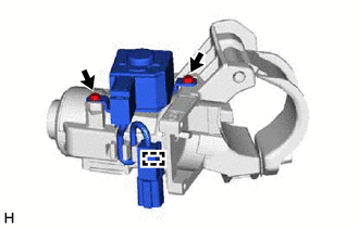
INSTALL UN-LOCK WARNING SWITCH ASSEMBLY (w/o Entry and Start System)
-
Engage the 2 claws to install the un-lock warning switch assembly to the upper steering column bracket assembly.
-
-
INSTALL IGNITION SWITCH LOCK CYLINDER ASSEMBLY (w/o Entry and Start System)
-
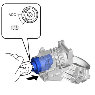
*1 LOCK Turn the ignition switch to ACC.
-
Install the ignition switch lock cylinder assembly to the upper steering column bracket assembly.
-
Make sure that the ignition switch lock cylinder assembly is securely installed into the upper steering column bracket assembly.
-
-
INSTALL KEY INTERLOCK SOLENOID (w/o Entry and Start System)
-
for CVT:
-
Connect the solenoid wire connector to the key interlock solenoid.
-
Install the key interlock solenoid to the upper steering column bracket assembly with the 2 screws.
-
Engage the clamp.
-
-
-
INSTALL IGNITION OR STARTER SWITCH ASSEMBLY (w/o Entry and Start System)
-
Install the ignition or starter switch assembly to the upper steering column bracket assembly with the 2 screws.
-
-
INSTALL TRANSPONDER KEY COIL (w/o Entry and Start System)
-
Engage the 2 claws to install the transponder key coil.
-
-
INSTALL UPPER STEERING COLUMN BRACKET WITH SWITCH ASSEMBLY (w/o Entry and Start System)
-
Set the steering column assembly in a vise between aluminum plates.
Note
Do not overtighten the vise.
-
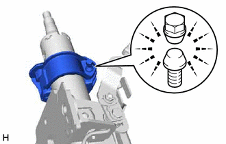
Temporarily install the upper steering column bracket with switch assembly with a new steering lock set bolt.
-
Tighten the steering lock set bolt until the bolt head breaks off.
-
-
INSTALL STEERING LOCK ACTUATOR ASSEMBLY (w/ Entry and Start System)
Tech Tips
-
Perform the same procedure as the upper steering column bracket with switch assembly.
-
When replacing the steering lock actuator assembly, refer to the service bulletin.
-
-
INSTALL NO. 1 STEERING COLUMN PROTECTOR (for Manual Transaxle RHD)
-
Install the No. 1 steering column protector with the bolt.
- Torque:
- 25 N*m { 255 kgf*cm, 18 ft.*lbf }
-