STEERING COLUMN ASSEMBLY DISASSEMBLY

PROCEDURE
-
REMOVE NO. 1 STEERING COLUMN PROTECTOR (for Manual Transaxle RHD)
-
Remove the bolt and No. 1 steering column protector from the steering column assembly.
-
-
REMOVE UPPER STEERING COLUMN BRACKET WITH SWITCH ASSEMBLY (w/o Entry and Start System)
-
Secure the steering column assembly in a vise between aluminum plates.
Note
Do not overtighten the vise.
-
Using a drill, drill a hole in the steering lock set bolt and insert a screw extractor.
-
Using the screw extractor, remove the steering lock set bolt and upper steering column bracket with switch assembly.
-
-
REMOVE STEERING LOCK ACTUATOR ASSEMBLY (w/ Entry and Start System)
Tech Tips
Perform the same procedure as the upper steering column bracket with switch assembly.
-
REMOVE TRANSPONDER KEY COIL (w/o Entry and Start System)
-
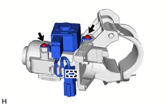
Disengage the 2 claws and remove the transponder key coil.
-
-
REMOVE IGNITION OR STARTER SWITCH ASSEMBLY (w/o Entry and Start System)
-
Remove the 2 screws and ignition or starter switch assembly from the upper steering column bracket assembly.
-
-
REMOVE KEY INTERLOCK SOLENOID (w/o Entry and Start System)
-
for CVT:
-
Disengage the clamp and remove the 2 screws and key interlock solenoid from the upper steering column bracket assembly.
-
Disconnect the solenoid wire connector from the key interlock solenoid and remove the solenoid wire.
-
-
-
REMOVE IGNITION SWITCH LOCK CYLINDER ASSEMBLY (w/o Entry and Start System)
-
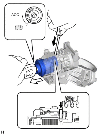
*1 LOCK 
Push 
Pull Turn the ignition switch to ACC.
-
Insert the tip of a screwdriver into the hole in the upper steering column bracket assembly, as shown in the illustration, and pull the ignition switch lock cylinder assembly.
-
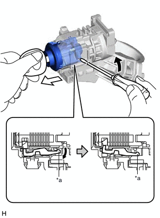
*a Claw Tilt Pull out Insert the tip of a screwdriver into the hole in the upper steering column bracket assembly and tilt it upward, as shown in the illustration, to disengage the claw on the ignition switch lock cylinder assembly. Then pull out the ignition switch lock cylinder assembly.
-
-
REMOVE UN-LOCK WARNING SWITCH ASSEMBLY (w/o Entry and Start System)
-
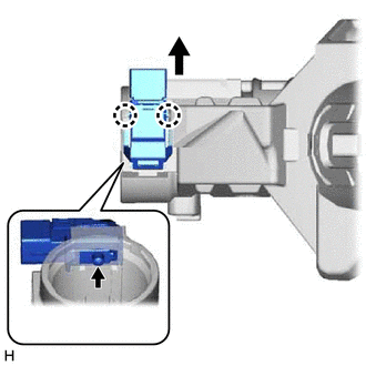
Disengage the 2 claws and remove the un-lock warning switch assembly.
-
-
REMOVE POWER STEERING ECU WITH MOTOR ASSEMBLY
Note
-
Do not drop the power steering ECU with motor assembly, strike it with tools or subject it to impacts.
-
If the power steering ECU with motor assembly is subjected to an impact, replace it with a new one.
-
Do not pull the wire harness of the power steering ECU with motor assembly.
-
Do not allow any moisture to come into contact with the power steering ECU with motor assembly.
-
Do not loosen any bolts not mentioned in the procedure.
-
Do not allow any foreign matter to contaminate the power steering ECU with motor assembly.
-
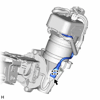
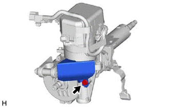
Disconnect the connector.
-
Disengage the wire harness clamp.
-
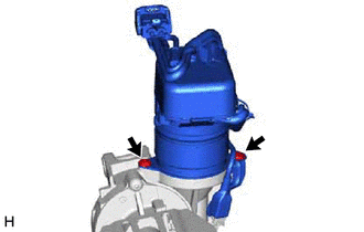
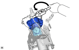
Using a T40 "TORX" socket wrench, Remove the 2 bolts, bracket and power steering ECU with motor assembly from the electric power steering column sub-assembly.
Tech Tips
If the bolts have been replaced in the past, the power steering ECU with motor assembly should be installed to the electric power steering column sub-assembly with hexagon bolts.
-
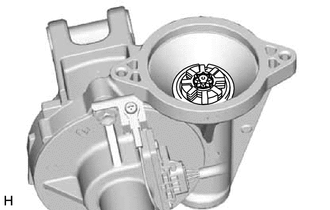
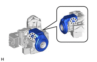
Remove the electric power steering motor shaft spacer from the electric power steering column sub-assembly.
-
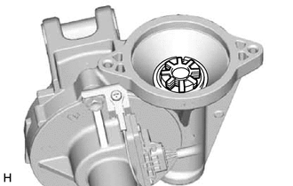
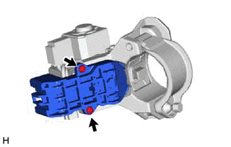
Remove the electric power steering motor shaft damper from the electric power steering column sub-assembly.
-