STEERING COLUMN ASSEMBLY REMOVAL

PROCEDURE
-
PRECAUTION
-
ALIGN FRONT WHEELS FACING STRAIGHT AHEAD
-
REMOVE HORN BUTTON ASSEMBLY
-
REMOVE STEERING WHEEL ASSEMBLY
-
REMOVE STEERING COLUMN COVER
-
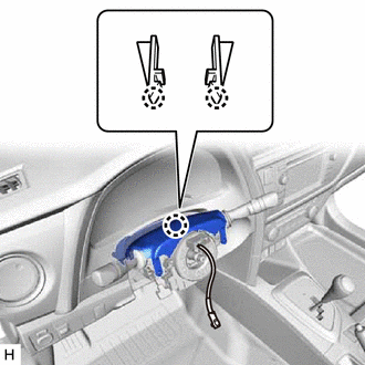
Remove the 2 screws.
-
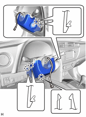
Disengage the 5 claws and remove the steering column cover (lower).
-
Disengage the 2 claws and remove the steering column cover (upper).
-
-
REMOVE TURN SIGNAL SWITCH ASSEMBLY WITH SPIRAL CABLE SUB-ASSEMBLY
Note
w/ VSC:
-
Do not replace the spiral cable with sensor sub-assembly with the battery connected and the ignition switch ON.
-
Do not rotate the spiral cable with sensor sub-assembly without the steering wheel with the battery connected and the ignition switch ON.
-
Ensure that the steering wheel is installed and aligned straight when inspecting the steering sensor.
-
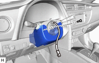
Disconnect each connector from the turn signal switch assembly with spiral cable sub-assembly.
-
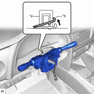
*a Clamp *b Claw Using pliers, expand the clamp.
-
While holding the clamp expanded, raise the claw using a screwdriver to disengage it, and then remove the turn signal switch assembly with spiral cable sub-assembly from the steering column assembly.
-
-
REMOVE COLUMN HOLE COVER SILENCER SHEET
-
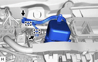
Turn back the floor carpet.
-
Remove the 2 clips and column hole cover silencer sheet.
-
-
SEPARATE NO. 2 STEERING INTERMEDIATE SHAFT ASSEMBLY
-
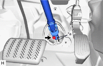
*a Matchmark Put matchmarks on the No. 2 steering intermediate shaft assembly and steering intermediate shaft assembly.
-
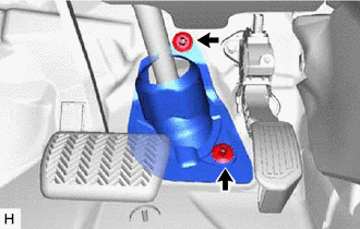
Remove the bolt.
-
Separate the No. 2 steering intermediate shaft assembly from the steering intermediate shaft assembly.
-
-
REMOVE NO. 2 STEERING INTERMEDIATE SHAFT ASSEMBLY
-
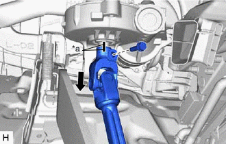
*a Matchmark Remove the bolt and slide the No. 2 steering intermediate shaft assembly.
Note
Do not separate the No. 2 steering intermediate shaft assembly from the steering column assembly.
-
Put matchmarks on the No. 2 steering intermediate shaft assembly and the steering column assembly.
-
Remove the No. 2 steering intermediate shaft assembly from the steering column assembly.
-
-
REMOVE BRAKE PEDAL SUPPORT ASSEMBLY
-
for LHD: Click here
-
for RHD: Click here
-
-
REMOVE UPPER INSTRUMENT PANEL ASSEMBLY
-
REMOVE LOWER INSTRUMENT CLUSTER FINISH PANEL ASSEMBLY (w/o Driver Side Knee Airbag)
-
for LHD: Click here
-
for RHD: Click here
-
-
REMOVE NO. 1 SWITCH HOLE BASE (w/o Driver Side Knee Airbag)
-
for LHD: Click here
-
for RHD: Click here
-
-
REMOVE NO. 1 INSTRUMENT PANEL UNDER COVER SUB-ASSEMBLY (w/o Driver Side Knee Airbag)
-
w/ Instrument Panel Under Cover:
-
-
REMOVE LOWER INSTRUMENT PANEL FINISH PANEL SUB-ASSEMBLY (w/o Driver Side Knee Airbag)
-
REMOVE LOWER NO. 1 INSTRUMENT PANEL AIRBAG ASSEMBLY (w/ Driver Side Knee Airbag)
-
REMOVE STEERING COLUMN ASSEMBLY
-
Disconnect the 2 connectors.
-
Disengage the 2 wire harness clamps.
-
Disconnect each connector and disengage each wire harness clamp from the steering column assembly.
-
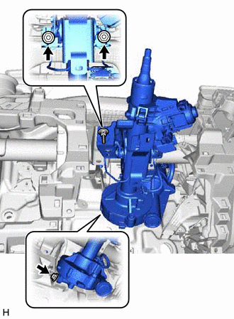
Remove the bolt, 2 nuts and steering column assembly.
-