POWER STEERING SYSTEM, Diagnostic DTC:C1551
| DTC Code | DTC Name |
|---|---|
| C1551 | IG Power Supply Voltage |
DESCRIPTION
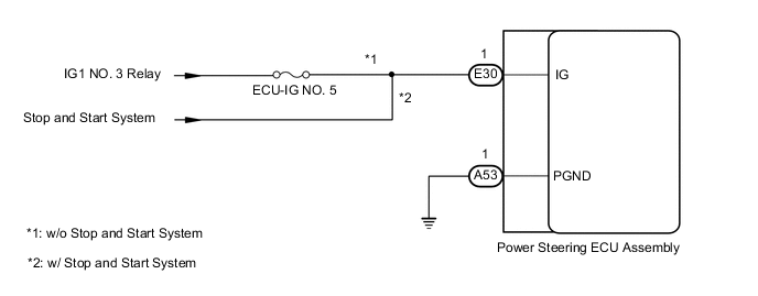
The power steering ECU assembly distinguishes the ignition switch status as ON or off through the IG power source circuit.
| DTC No. | Detection Item | DTC Detection Condition | Trouble Area | Warning Indicate | Return-to-normal Condition | Note |
|---|---|---|---|---|---|---|
| C1551 | IG Power Supply Voltage | Open or short in IG power source circuit with ignition switch ON |
|
EPS Warning Light: Comes on | After normal confirmation | - |
WIRING DIAGRAM
CAUTION / NOTICE / HINT
Note
If the power steering ECU assembly has been replaced with a new one, perform assist map writing and torque sensor zero point calibration.
Tech Tips
Inspect the fuses for circuits related to this system before performing the following procedure.
PROCEDURE
-
READ VALUE USING GTS
-
Turn the ignition switch off.
-
Connect the GTS to the DLC3.
-
Turn the ignition switch to ON.
-
Turn the GTS on.
-
Enter the following menus: Chassis / EMPS / Data List.
-
Select the item "IG Power Supply" in the Data List and read the value displayed on the GTS.
Chassis > EMPS > Data ListTester Display Measurement Item Range Normal Condition Diagnostic Note IG Power Supply IG power source voltage Min.: 0.0000 V
Max.: 20.1531 V
8 to 16 V Ignition switch ON
Chassis > EMPS > Data ListTester Display IG Power Supply OK The normal condition value is displayed on the GTS. Result Proceed to OK NG
OK 
REPLACE POWER STEERING ECU ASSEMBLY Click here
NG 
-
-
CHECK HARNESS AND CONNECTOR (BATTERY - POWER STEERING ECU ASSEMBLY)
-
Disconnect the E30 and A53 power steering ECU assembly connectors.
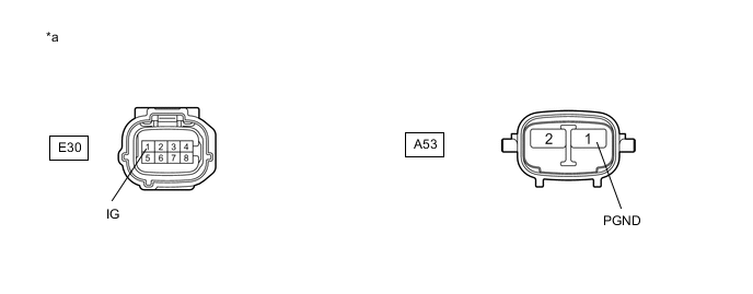
*a Front view of wire harness connector
(to Power Steering ECU Assembly)
- - -
Measure the voltage according to the value(s) in the table below.
Standard Voltage Tester Connection Condition Specified Condition E30-1(IG) - Body ground Ignition switch ON 9 to 16 V -
Measure the resistance according to the value(s) in the table below.
Standard Resistance Tester Connection Condition Specified Condition A53-1 (PGND) - Body ground Always Below 1 Ω Result Proceed to OK NG
OK
REPLACE POWER STEERING ECU ASSEMBLY Click here
NG
REPAIR OR REPLACE HARNESS OR CONNECTOR
-