BRAKE PEDAL(for LHD) INSTALLATION
PROCEDURE
-
INSTALL BRAKE PEDAL SUPPORT ASSEMBLY
-
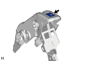
Install the nut to the brake pedal support assembly.
-
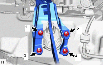
Install the brake pedal support assembly with the 4 nuts.
- Torque:
- 12.7 N*m { 130 kgf*cm, 9 ft.*lbf }
Note
Tighten the 4 nuts in the order shown in the illustration.
-
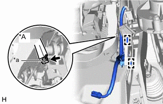
*A for 1AD-FTV *a Brake Pedal Load Sensing Switch Connector for 1AD-FTV:
Connect the brake pedal load sensing switch connector.
-
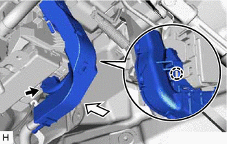
Engage the 2 clamps to install the wire harness to the brake pedal support assembly.
-
Install the brake pedal support assembly to the instrument panel reinforcement assembly with the bolt.
- Torque:
- 23.6 N*m { 241 kgf*cm, 17 ft.*lbf }
-
Connect the connector to the main body ECU.
-
Engage the claw to install the wire harness protector to the instrument panel junction block assembly.
-
-
INSTALL PUSH ROD PIN
-

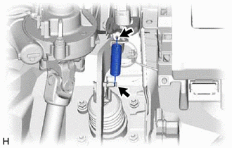
Lithium Soap Base Glycol Grease Apply lithium soap base glycol grease to the push rod pin and installation hole of the brake pedal support assembly.
-
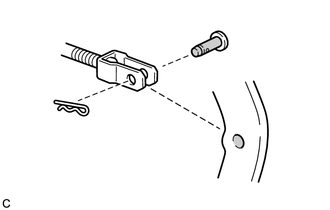
Connect the brake master cylinder push rod clevis to the brake pedal support assembly with the push rod pin as shown in the illustration and install a new clip.
Note
Install the push rod pin in the correct direction.
-
-
INSTALL BRAKE PEDAL RETURN SPRING
-
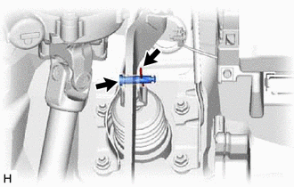
Install the brake pedal return spring to the brake pedal support assembly and push rod pin.
-
-
CONNECT NO. 2 STEERING INTERMEDIATE SHAFT ASSEMBLY (for 1AD-FTV)
-
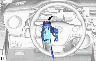
Connect the No. 2 steering intermediate shaft assembly to the steering column assembly.
-
-
INSTALL STOP LIGHT SWITCH MOUNTING ADJUSTER
-
INSTALL STOP LIGHT SWITCH ASSEMBLY
-
INSTALL NO. 1 INSTRUMENT PANEL UNDER COVER SUB-ASSEMBLY (w/ Instrument Panel Under Cover)
-
INSTALL LOWER NO. 1 INSTRUMENT PANEL AIRBAG ASSEMBLY (w/ Driver Side Knee Airbag)
-
INSTALL COMBINATION METER ASSEMBLY
-
INSPECT AND ADJUST BRAKE PEDAL