BRAKE ACTUATOR INSTALLATION
PROCEDURE
-
INSTALL BRAKE ACTUATOR ASSEMBLY
-
for Type A Brake Actuator Assembly:
-
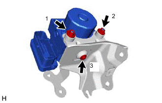
Install the brake actuator assembly to the brake actuator bracket assembly with the bolt and 2 new nuts.
- Torque:
- Bolt
- 5.4 N*m { 55 kgf*cm, 48 in.*lbf }
- Nut
- 7.5 N*m { 76 kgf*cm, 66 in.*lbf }
Note
-
Do not remove the hole plugs of a new brake actuator assembly before connecting the brake lines because the brake actuator assembly is filled with brake fluid.
-
Do not hold the brake actuator assembly by the connector.
-
Tighten the bolt and 2 nuts in the order shown in the illustration.
-
-
for Type B Brake Actuator Assembly:
-
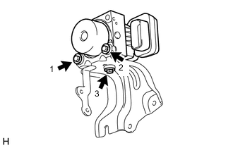
Install the brake actuator assembly to the brake actuator bracket assembly with the 3 bolts.
- Torque:
- 5.4 N*m { 55 kgf*cm, 48 in.*lbf }
Note
-
Do not remove the hole plugs of a new brake actuator assembly before connecting the brake lines because the brake actuator assembly is filled with brake fluid.
-
Do not hold the brake actuator assembly by the connector.
-
Tighten the 3 bolts in the order shown in the illustration.
-
-
-
INSTALL BRAKE ACTUATOR WITH BRACKET
-
for Type A Brake Actuator Assembly:
-
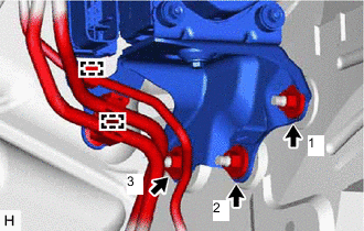
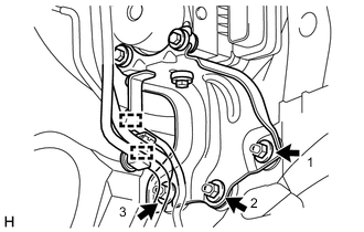
Install the brake actuator with bracket to the vehicle body with 3 new nuts.
- Torque:
- 19 N*m { 194 kgf*cm, 14 ft.*lbf }
Note
-
Do not damage the brake lines, fuel lines or wire harness.
-
Tighten the 3 nuts in the order shown in the illustration.
-
Engage each clamp to install the No. 2 fuel tube clamp and front No. 4 brake tube to the brake actuator bracket assembly.
Note
Do not damage the brake lines or fuel lines.
-
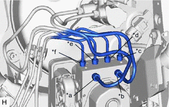
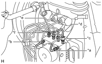
*a for LHD:
From 1st Chamber of Master Cylinder Sub-assembly
for RHD:
From 2nd Chamber of Master Cylinder Sub-assembly
*b for LHD:
From 2nd Chamber of Master Cylinder Sub-assembly
for RHD:
From 1st Chamber of Master Cylinder Sub-assembly
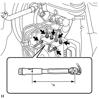
*c To Front Wheel Cylinder Assembly RH *d To Rear Wheel Cylinder Assembly LH *e To Rear Wheel Cylinder Assembly RH *f To Front Wheel Cylinder Assembly LH Temporarily tighten each brake line to the correct position on the brake actuator assembly as shown in the illustration.
-
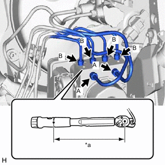
*a Torque Wrench Fulcrum Length Using a union nut wrench, fully tighten each brake line.
- Torque:
- Specified tightening torque (A) (w/o VSC)
- 15.2 N*m { 155 kgf*cm, 11 ft.*lbf }
- Specified tightening torque (A) (w/ VSC)
- 19.5 N*m { 199 kgf*cm, 14 ft.*lbf }
- Specified tightening torque (B)
- 15.2 N*m { 155 kgf*cm, 11 ft.*lbf }
Tech Tips
-
Calculate the torque wrench reading when changing the fulcrum length of the torque wrench.
-
When using a union nut wrench (fulcrum length of 20 mm (0.787 in.)) + torque wrench (fulcrum length of 162 mm (6.38 in.)):
w/ VSC (A): 17.36 N*m (177 kgf*cm, 13 ft.*lbf)
-
When using a union nut wrench (fulcrum length of 22 mm (0.866 in.)) + torque wrench (fulcrum length of 162 mm (6.38 in.)):
w/o VSC (A), (B): 13.38 N*m (136 kgf*cm, 10 ft.*lbf)
-
Engage the clamp to install the wire harness to the brake actuator bracket assembly.
-
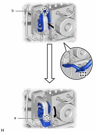
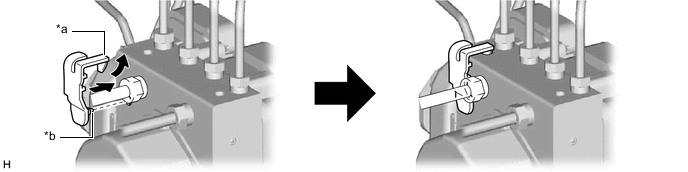
Connect the connector to the brake actuator assembly and disengage the claw (b).
-
Pull the lever down and engage the claw (a) to engage the connector lock.
Note
-
Make sure that the connector is locked securely.
-
Make sure that the actuator connector can be connected smoothly. Do not allow water, oil or dirt to enter the connector.
-
-
-
for Type B Brake Actuator Assembly:
-
Install the brake actuator with bracket to the vehicle body with the 3 nuts.
- Torque:
- 19 N*m { 194 kgf*cm, 14 ft.*lbf }
Note
-
Do not damage the brake lines, fuel lines or wire harness.
-
Tighten the 3 nuts in the order shown in the illustration.
-
Engage each clamp to install the No. 2 fuel tube clamp and front No. 4 brake tube to the brake actuator bracket assembly.
Note
Do not damage the brake lines or fuel lines.
-
*a From 1st Chamber of Master Cylinder Sub-assembly *b From 2nd Chamber of Master Cylinder Sub-assembly *c To Front Wheel Cylinder Assembly LH *d To Rear Wheel Cylinder Assembly RH *e To Rear Wheel Cylinder Assembly LH *f To Front Wheel Cylinder Assembly RH Temporarily tighten each brake line to the correct position on the brake actuator assembly as shown in the illustration.
-
*a Torque Wrench Fulcrum Length Using a union nut wrench, fully tighten each brake line.
- Torque:
- Specified tightening torque
- 15.2 N*m { 155 kgf*cm, 11 ft.*lbf }
Tech Tips
-
Calculate the torque wrench reading when changing the fulcrum length of the torque wrench.
-
When using a union nut wrench (fulcrum length of 22 mm (0.866 in.)) + torque wrench (fulcrum length of 162 mm (6.38 in.)):
13.38 N*m (136 kgf*cm, 10 ft.*lbf)
-

Connect 
Lock Connect the connector to the brake actuator assembly and lock the lock lever.
Note
-
Make sure that the connector is locked securely.
-
Make sure that the actuator connector can be connected smoothly. Do not allow water, oil or dirt to enter the connector.
-
-
-
Connect the connector to the ECM.
for 1NR-FE: Click here
for 1ZR-FE: Click here
for 1ZR-FAE: Click here
for 2ZR-FE: Click here
for 8NR-FTS: Click here
-
-
INSTALL BRAKE ACTUATOR COVER (for 1WW, 1ND-TV with VSC)
-
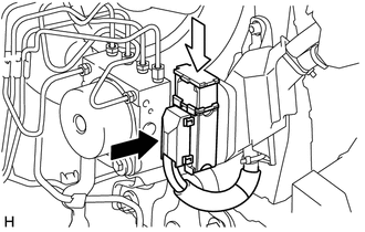
Raise the claw of a new brake actuator cover, insert the pin into the hole and engage the claw to install it to the brake actuator assembly.
*a Claw *b Pin
-
-
INSTALL AIR CLEANER BRACKET (for 1WW, 1ND-TV)
-
Install the air cleaner bracket with the 3 bolts.
- Torque:
- 7.0 N*m { 71 kgf*cm, 62 in.*lbf }
-
-
INSTALL FUEL FILTER SUPPORT (for 1WW, 1ND-TV)
-
Install the fuel filter support with the 3 bolts.
- Torque:
- 17.5 N*m { 178 kgf*cm, 13 ft.*lbf }
-
Engage the wire harness clamp to the fuel filter support.
-
-
INSTALL GLOW PLUG RELAY ASSEMBLY (for 1WW, 1ND-TV)
-
Install the glow plug relay assembly to the fuel filter support with the bolt.
- Torque:
- for 1ND-TV
- 11 N*m { 112 kgf*cm, 8 ft.*lbf }
- for 1WW
- 17.5 N*m { 178 kgf*cm, 13 ft.*lbf }
-
Connect the wire harness clamp to the fuel filter support.
-
-
CONNECT WIRE HARNESS (for 1ND-TV)
-
Connect the ECM connector to the ECM.
w/o Glow Plug Controller: Click here
w/ Glow Plug Controller: Click here
-
Connect the 3 wire harness clamps to the fuel filter support.
-
-
CONNECT WIRE HARNESS (for 1WW)
-
Connect the ECM connector to the ECM.
-
Connect the 2 wire harness clamps to the fuel filter support.
-
Connect the connector.
-
-
INSTALL FUEL FILTER ASSEMBLY (for 1WW, 1ND-TV)
for 1WW: Click here
for 1ND-TV: Click here
-
INSTALL NO. 1 FUEL FILTER PROTECTOR (for 1WW)
-
INSTALL AIR CLEANER CASE SUB-ASSEMBLY (for 1NR-FE)
-
INSTALL AIR CLEANER CAP SUB-ASSEMBLY (for 1NR-FE)
-
INSTALL NO. 1 ENGINE COVER (for 1NR-FE)
-
INSTALL AIR CLEANER CASE SUB-ASSEMBLY (for 1ZR-FE)
-
INSTALL AIR CLEANER CAP SUB-ASSEMBLY (for 1ZR-FE)
-
INSTALL NO. 2 CYLINDER HEAD COVER (for 1ZR-FE)
-
INSTALL AIR CLEANER CASE SUB-ASSEMBLY (for 1ZR-FAE)
-
INSTALL AIR CLEANER CAP SUB-ASSEMBLY (for 1ZR-FAE)
-
INSTALL NO. 2 CYLINDER HEAD COVER (for 1ZR-FAE)
-
INSTALL AIR CLEANER CASE SUB-ASSEMBLY (for 2ZR-FE)
-
INSTALL AIR CLEANER CAP SUB-ASSEMBLY (for 2ZR-FE)
-
INSTALL NO. 2 CYLINDER HEAD COVER (for 2ZR-FE)
-
INSTALL AIR CLEANER CASE SUB-ASSEMBLY (for 1ND-TV)
w/o Glow Plug Controller: Click here
w/ Glow Plug Controller: Click here
-
INSTALL AIR CLEANER CAP SUB-ASSEMBLY (for 1ND-TV)
w/o Glow Plug Controller: Click here
w/ Glow Plug Controller: Click here
-
INSTALL NO. 1 ENGINE COVER (for 1ND-TV with No. 1 Engine Cover)
w/o Glow Plug Controller: Click here
w/ Glow Plug Controller: Click here
-
INSTALL AIR CLEANER CASE SUB-ASSEMBLY (for 8NR-FTS)
-
INSTALL AIR CLEANER CAP WITH AIR CLEANER HOSE (for 8NR-FTS)
-
INSTALL AIR CLEANER CASE SUB-ASSEMBLY (for 1WW)
-
INSTALL AIR CLEANER CAP SUB-ASSEMBLY WITH AIR CLEANER HOSE ASSEMBLY (for 1WW)
-
INSTALL NO. 1 ENGINE COVER (for 1WW)
-
CONNECT CABLE TO NEGATIVE BATTERY TERMINAL
Note
When disconnecting the cable, some systems need to be initialized after the cable is reconnected.
-
BLEED AIR FROM FUEL SYSTEM (for 1ND-TV)
-
CHECK FUEL PUMP OPERATION AND INSPECT FOR FUEL LEAK (for 1WW)
-
INSPECT FOR FUEL LEAK (for 1ND-TV)
w/o Glow Plug Controller: Click here
w/ Glow Plug Controller: Click here
-
BLEED BRAKE SYSTEM
-
INSPECT BRAKE ACTUATOR USING GTS
-
PERFORM SYSTEM VARIANT LEARNING (w/ VSC)
-
CHECK FOR AND CLEAR DTCS
w/o VSC (for Type A): Click here
w/o VSC (for Type B): Click here
w/ VSC: Click here