VEHICLE STABILITY CONTROL SYSTEM, Diagnostic DTC:C1246, C1281

| DTC Code | DTC Name |
|---|---|
| C1246 | Master Cylinder Pressure Sensor Malfunction |
| C1281 | Master Cylinder Pressure Sensor Output Malfunction (Test Mode DTC) |
DESCRIPTION
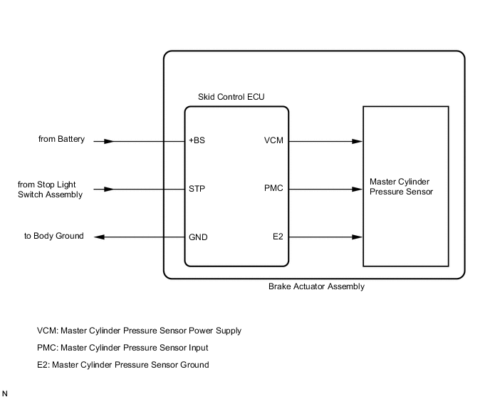
The master cylinder pressure sensor is connected to the skid control ECU in the brake actuator assembly. DTC C1281 is cleared when the Lost Booster Pressure Judgment Check is performed correctly in Test Mode and the check indicates a pass, or when Test Mode ends. DTC C1281 is output only in Test Mode.
| DTC No. | Detection Item | DTC Detection Condition | Trouble Area |
|---|---|---|---|
| C1246 | Master Cylinder Pressure Sensor Malfunction | Any of the following is detected:
|
|
| C1281 | Master Cylinder Pressure Sensor Output Malfunction (Test Mode DTC) | Detected only during Test Mode. |
|
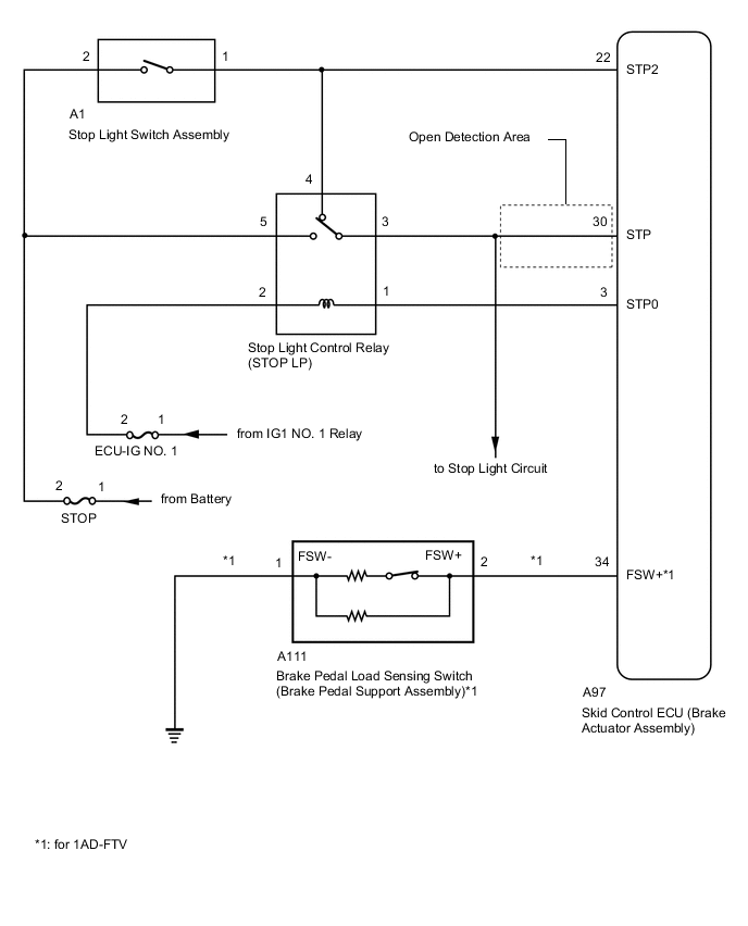
WIRING DIAGRAM
CAUTION / NOTICE / HINT
Note
When replacing the skid control ECU (brake actuator assembly), perform system variant learning.
PROCEDURE
-
CHECK STOP LIGHT OPERATION
-
Check that the stop lights come on when the brake pedal is depressed, and go off when the brake pedal is released.
OK Condition Illumination Condition Brake pedal depressed. On Brake pedal released. Off Result Proceed to OK NG
NG 
INSPECT LIGHTING SYSTEM (STOP LIGHT CIRCUIT) Click here
OK 
-
-
READ VALUE USING GTS (MASTER CYLINDER PRESSURE SENSOR)
-
Connect the GTS to the DLC3.
-
Start the engine.
-
Select the Data List using the GTS.
Chassis > ABS/VSC/TRC > Data ListTester Display Measurement Item Range Normal Condition Diagnostic Note Master Cylinder Sensor Master cylinder pressure sensor reading Min.: 0.00 V, Max.: 5.00 V When brake pedal released: 0.2 to 0.4 V Reading increases when brake pedal is depressed
Chassis > ABS/VSC/TRC > Data ListTester Display Master Cylinder Sensor -
Check that the brake fluid pressure value of the master cylinder pressure sensor observed on the GTS changes when the brake pedal is depressed.
OK When the pedal is depressed, the voltage displayed on the GTS increases. Result Result Proceed to OK (for 1AD-FTV) A OK (except 1AD-FTV) B NG C
B 
READ VALUE USING GTS (STOP LIGHT SWITCH ASSEMBLY) Click here
C
REPLACE BRAKE ACTUATOR ASSEMBLY Click here
A
-
-
READ VALUE USING GTS (STOP LIGHT SWITCH ASSEMBLY AND BRAKE PEDAL LOAD SENSING SWITCH)
-
Select the Data List using the GTS.
Chassis > ABS/VSC/TRC > Data ListTester Display Measurement Item Range Normal Condition Diagnostic Note Stop Light SW Stop light switch ON or OFF ON: Brake pedal depressed
OFF: Brake pedal released
- Brake Pedal Load Sensing SW Brake pedal load sensing switch ON or OFF ON: Brake pedal depressed beyond a specified point
OFF: Brake pedal not depressed beyond a specified point
-
Chassis > ABS/VSC/TRC > Data ListTester Display Stop Light SW Brake Pedal Load Sensing SW -
Check that the stop light switch display and brake pedal load sensing switch display observed on the GTS change according to brake pedal operation.
OK The GTS displays ON or OFF according to brake pedal operation. -
Slowly depress the brake pedal, and check when the stop light switch and brake pedal load sensing switch turn on.
OK First the stop light switch turns on, and then the brake pedal load sensing switch turns on. Result Result Proceed to OK A NG (The stop light switch does not turn on.) B NG (Turning on of the brake pedal load sensing switch is not confirmed.) C NG (The brake pedal load sensing switch turns on first.) D
B
CHECK HARNESS AND CONNECTOR (STP TERMINAL) Click here
C
INSPECT BRAKE PEDAL LOAD SENSING SWITCH Click here
D
CHECK BRAKE PEDAL AND STOP LIGHT SWITCH ASSEMBLY INSTALLATION Click here
A
-
-
RECONFIRM DTC
-
Turn the ignition switch off.
-
Clear the DTCs.
Chassis > ABS/VSC/TRC > Clear DTCs -
Turn the ignition switch off.
-
Start the engine.
-
Drive the vehicle at a speed of 30 km/h (18 mph) or more and perform a braking test (decelerate the vehicle by depressing the brake pedal).
-
Check if the same DTC is output.
Chassis > ABS/VSC/TRC > Trouble CodesResult Result Proceed to DTC C1246 is not output. A DTC C1246 is output. B
A
USE SIMULATION METHOD TO CHECK Click here
B
REPLACE BRAKE ACTUATOR ASSEMBLY Click here
-
-
CHECK HARNESS AND CONNECTOR (STP TERMINAL)
-
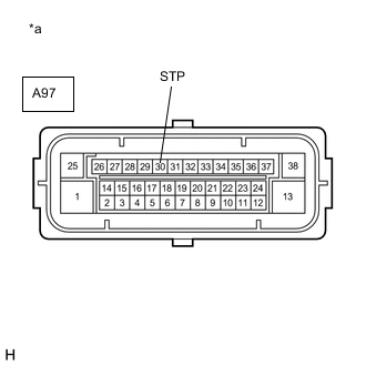
*a Front view of wire harness connector
(to Skid Control ECU (Brake Actuator Assembly))
Turn the ignition switch off.
-
Make sure that there is no looseness at the locking part and the connecting part of the connector.
-
Disconnect the A97 skid control ECU (brake actuator assembly) connector.
-
Measure the voltage according to the value(s) in the table below.
Standard Voltage Tester Connection Condition Specified Condition A97-30 (STP) - Body ground Stop light switch ON (Brake pedal depressed) 11 to 14 V* A97-30 (STP) - Body ground Stop light switch OFF (Brake pedal released) Below 1.5 V Tech Tips
*: The standard voltage value varies depending on the +BS terminal voltage value. The standard voltage is 85% of the +BS terminal voltage.
Result Proceed to OK NG
OK
REPLACE BRAKE ACTUATOR ASSEMBLY Click here
NG
REPAIR OR REPLACE HARNESS OR CONNECTOR (STP CIRCUIT)
-
-
INSPECT BRAKE PEDAL LOAD SENSING SWITCH
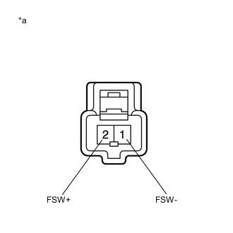
*a Component without harness connected
(Brake Pedal Load Sensing Switch (Brake Pedal Support Assembly))
-
Turn the ignition switch off.
-
Make sure that there is no looseness at the locking part and the connecting part of the connector.
-
Disconnect the A111 brake pedal load sensing switch connector.
Note
-
Do not remove the brake pedal load sensing switch from the brake pedal support assembly.
-
When there is a malfunction in the brake pedal load sensing switch, replace the brake pedal support assembly.
-
-
Measure the resistance according to the value(s) in the table below.
Standard Resistance Tester Connection Condition Specified Condition 2 (FSW+) - 1 (FSW-) Switch OFF
(Brake pedal depressed)
950 to 1050 Ω 2 (FSW+) - 1 (FSW-) Switch ON
(Brake pedal released)
203 to 223 Ω Result Proceed to OK NG
NG
REPLACE BRAKE PEDAL SUPPORT ASSEMBLY for LHD: Click here
REPLACE BRAKE PEDAL SUPPORT ASSEMBLY for RHD: Click hereOK
-
-
CHECK HARNESS AND CONNECTOR (BRAKE ACTUATOR ASSEMBLY - BRAKE PEDAL LOAD SENSING SWITCH)
-
Make sure that there is no looseness at the locking part and the connecting part of the connector.
-
Disconnect the A97 skid control ECU (brake actuator assembly) connector.
-
Measure the resistance according to the value(s) in the table below.
Standard Resistance Tester Connection Condition Specified Condition A97-34 (FSW+) - A111-2 (FSW+) Always Below 1 Ω A97-34 (FSW+) or A111-2 (FSW+) - Body ground Always 10 kΩ or higher A111-1 (FSW-) - Body ground Always Below 1 Ω Result Proceed to OK NG
OK
REPLACE BRAKE ACTUATOR ASSEMBLY Click here
NG
REPAIR OR REPLACE HARNESS OR CONNECTOR
-
-
CHECK BRAKE PEDAL AND STOP LIGHT SWITCH ASSEMBLY INSTALLATION
-
Turn the ignition switch off.
-
Check the brake pedal height and stop light switch assembly installation.
for LHD: Click here
for RHD: Click here
OK The brake pedal height and stop light switch assembly installation are normal. Result Proceed to OK NG
OK
REPLACE BRAKE PEDAL SUPPORT ASSEMBLY for LHD: Click here
REPLACE BRAKE PEDAL SUPPORT ASSEMBLY for RHD: Click hereNG
ADJUST BRAKE PEDAL OR STOP LIGHT SWITCH ASSEMBLY for LHD: Click here
ADJUST BRAKE PEDAL OR STOP LIGHT SWITCH ASSEMBLY for RHD: Click here -
-
READ VALUE USING GTS (STOP LIGHT SWITCH ASSEMBLY)
-
Connect the GTS to the DLC3.
-
Turn the ignition switch to ON.
-
Select the Data List using the GTS.
Chassis > ABS/VSC/TRC > Data ListTester Display Measurement Item Range Normal Condition Diagnostic Note Stop Light SW Stop light switch ON or OFF ON: Brake pedal depressed
OFF: Brake pedal released
-
Chassis > ABS/VSC/TRC > Data ListTester Display Stop Light SW -
Check that the stop light switch display observed on the GTS changes according to brake pedal operation.
OK The GTS displays ON or OFF according to brake pedal operation. Result Proceed to OK NG
NG
CHECK HARNESS AND CONNECTOR (STP TERMINAL) Click here
OK
-
-
RECONFIRM DTC
-
Turn the ignition switch off.
-
Clear the DTCs.
Chassis > ABS/VSC/TRC > Clear DTCs -
Turn the ignition switch off.
-
Start the engine.
-
Drive the vehicle and depress the brake pedal several times to test the stop light circuit.
-
Check if the same DTC is output.
Chassis > ABS/VSC/TRC > Trouble CodesResult Result Proceed to DTC C1246 is not output. A DTC C1246 is output. B Tech Tips
If troubleshooting has been carried out according to Problem Symptoms Table, refer back to the table and proceed to the next step before replacing parts.
A
USE SIMULATION METHOD TO CHECK Click here
B
REPLACE BRAKE ACTUATOR ASSEMBLY Click here
-
-
CHECK HARNESS AND CONNECTOR (STP TERMINAL)
-
*a Front view of wire harness connector
(to Skid Control ECU (Brake Actuator Assembly))
Turn the ignition switch off.
-
Make sure that there is no looseness at the locking part and the connecting part of the connector.
-
Disconnect the A97 skid control ECU (brake actuator assembly) connector.
-
Measure the voltage according to the value(s) in the table below.
Standard Voltage Tester Connection Condition Specified Condition A97-30 (STP) - Body ground Stop light switch ON (Brake pedal depressed) 11 to 14 V* A97-30 (STP) - Body ground Stop light switch OFF (Brake pedal released) Below 1.5 V Tech Tips
*: The standard voltage value varies depending on the +BS terminal voltage value. The standard voltage is 85% of the +BS terminal voltage.
Result Proceed to OK NG Tech Tips
If troubleshooting has been carried out according to Problem Symptoms Table, refer back to the table and proceed to the next step before replacing parts.
OK
REPLACE BRAKE ACTUATOR ASSEMBLY Click here
NG
REPAIR OR REPLACE HARNESS OR CONNECTOR (STP CIRCUIT)
-