ANTI-LOCK BRAKE SYSTEM(for Type A), Diagnostic DTC:C1300

| DTC Code | DTC Name |
|---|---|
| C1300 | Skid Control ECU Malfunction |
DESCRIPTION
The skid control ECU (brake actuator assembly) stores this DTC if malfunctions are found in a circuit inside the ECU by self diagnosis.
| DTC No. | Detection Item | DTC Detection Condition | Trouble Area |
|---|---|---|---|
| C1300 | Skid Control ECU Malfunction | Internal failure of the skid control ECU (brake actuator assembly). | Skid control ECU (brake actuator assembly) |
PROCEDURE
-
CHECK IF BRAKE ACTUATOR ASSEMBLY CONNECTOR IS SECURELY CONNECTED
-
Check if the skid control ECU (brake actuator assembly) connector is securely connected.
OK The connector is securely connected. Result Proceed to OK NG
NG 
CONNECT CONNECTOR TO ECU CORRECTLY
OK 
-
-
CHECK BATTERY
-
Check the battery voltage.
Standard Voltage 11 to 14 V Result Proceed to OK NG
NG
CHECK OR REPLACE CHARGING SYSTEM COMPONENT OR BATTERY for 1NR-FE: Click here
CHECK OR REPLACE CHARGING SYSTEM COMPONENT OR BATTERY for 1ZR-FE: Click here
CHECK OR REPLACE CHARGING SYSTEM COMPONENT OR BATTERY for 1ND-TV: Click here
CHECK OR REPLACE CHARGING SYSTEM COMPONENT OR BATTERY for 2ZR-FE: Click hereOK
-
-
CHECK HARNESS AND CONNECTOR (POWER SOURCE TERMINAL)
-
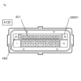
*a Front view of wire harness connector
(to Skid Control ECU (Brake Actuator Assembly))
Disconnect the A120 skid control ECU (brake actuator assembly) connector.
-
Measure the voltage according to the value(s) in the table below.
Standard Voltage Tester Connection Condition Specified Condition A120-25 (+BS) - Body ground Always 11 to 14 V A120-25 (+BS) - A120-38 (GND1) Always 11 to 14 V A120-28 (IG1) - Body ground Ignition switch ON 11 to 14 V A120-28 (IG1) - A120-38 (GND1) Ignition switch ON 11 to 14 V Result Proceed to OK NG
NG
REPAIR OR REPLACE HARNESS OR CONNECTOR (POWER SOURCE TERMINAL)
OK
-
-
CHECK HARNESS AND CONNECTOR (GND1 TERMINAL)
-
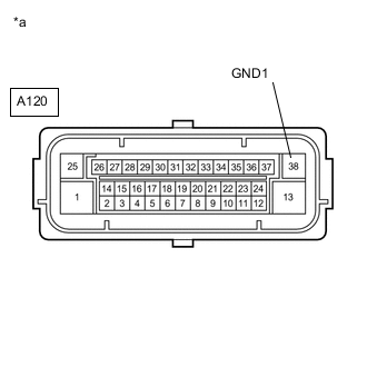
*a Front view of wire harness connector
(to Skid Control ECU (Brake Actuator Assembly))
Turn the ignition switch off.
-
Measure the resistance according to the value(s) in the table below.
Standard Resistance Tester Connection Condition Specified Condition A120-38 (GND1) - Body ground Always Below 1 Ω Result Proceed to OK NG
NG
REPAIR OR REPLACE HARNESS OR CONNECTOR (GND1 CIRCUIT)
OK
-
-
REPLACE BRAKE ACTUATOR ASSEMBLY
-
Replace the skid control ECU (brake actuator assembly).
Tech Tips
This DTC is output when the skid control ECU (brake actuator assembly) detects a malfunction in an internal circuit.
-
Perform the sensor check using the Test Mode procedure.
Chassis > ABS/VSC/TRC > UtilityTester Display Test Mode Result Proceed to NEXT
NEXT
END
-