ANTI-LOCK BRAKE SYSTEM TEST MODE PROCEDURE

-
WARNING LIGHT INITIAL CHECK
-
Release the parking brake.
Note
Before releasing the parking brake, move the shift lever to P for safety (for continuously variable transaxle), move the shift lever to N for safety (for multi-mode manual transaxle) or use wheel chocks to secure the vehicle (for manual transaxle).
Tech Tips
When the parking brake is applied or the brake fluid level is low, the brake warning light comes on.
-
When the ignition switch is turned to ON, check that the ABS warning and brake warning lights come on for approximately 3 seconds.
Tech Tips
-
If the skid control ECU (brake actuator assembly) stores a DTC, the ABS warning light will come on.
-
If any of the indicators remains on or does not come on, proceed to troubleshooting for the light circuits listed below.
Trouble Area See Procedure ABS warning light circuit (Remains on) ABS warning light circuit (Does not come on) Brake warning light circuit (Remains on) Brake warning light circuit (Does not come on) -
-
-
SENSOR CHECK USING TEST MODE (SIGNAL CHECK) (When Using GTS)
Tech Tips
DTCs are stored if any malfunctions are detected during the check of each sensor.
-
Procedure to enter Test Mode
-
Turn the ignition switch off.
-
Check that the steering wheel is centered.
-
for Continuously Variable Transaxle:
Check that the shift lever is in P.
-
for Manual Transaxle:
Apply the parking brake.
-
for Multi-Mode Manual Transaxle:
Make sure that the shift lever is in N.
-
Connect the GTS to the DLC3.
-
Turn the ignition switch to ON.
-
Turn the GTS on.
-
Switch the skid control ECU (brake actuator assembly) to Test Mode using the GTS. Enter the following menus: Chassis / ABS/VSC/TRC / Utility / Signal Check.
Chassis > ABS/VSC/TRC > UtilityTester Display Signal Check -
Check that the ABS warning light comes on for several seconds and then blinks in the Test Mode pattern.
Tech Tips
If the ABS warning light does not blink, inspect the ABS warning light circuit.
-
Check the ABS sensor.
Tech Tips
Check that the ABS warning light is blinking in the Test Mode pattern before performing the following ABS sensor check.
-
-
Speed Sensor Check
-
Drive the vehicle straight-ahead.
Accelerate the vehicle to a speed of 45 km/h (28 mph) or more for several seconds.
Tech Tips
-
The speed sensor check may not complete if wheelspin occurs.
-
The speed sensor check may not complete if the speed sensor check is started while turning the steering wheel.
Note
After the ABS warning light goes off, if the vehicle speed exceeds 80 km/h (50 mph), a sensor check code will be stored again.
Decelerate or stop the vehicle before the speed reaches 80 km/h (50 mph).
-
-
Check that the ABS warning light goes off.
Tech Tips
-
The ABS warning light goes off when the sensor check has completed.
-
The ABS warning light comes on immediately after a malfunction has been detected during the speed sensor check.
-
-
Stop the vehicle.
Tech Tips
When the sensor check has completed, the ABS warning light goes off while the vehicle is being driven, and blinks in the Test Mode pattern while the vehicle is stopped.
Note
If the sensor check has not completed, the ABS warning light will blink while the vehicle is being driven and the ABS will not operate.
-
-
End of Sensor Check
-
If the sensor checks have completed, the ABS warning light blinks in the Test Mode pattern when the vehicle is stopped and the ABS warning light goes off while the vehicle is being driven.
Note
If the sensor checks have not completed, the ABS warning light will blink while the vehicle is being driven and the ABS will not operate.
-
-
Reading Sensor Check DTCs
-
Read the DTC(s) by following the GTS screen.
Note
-
If only DTCs other than Test Mode sensor check DTCs are displayed, repair the malfunctions and clear the DTCs.
-
If Test Mode sensor check DTCs and other DTCs are displayed or if only Test Mode sensor check DTCs are displayed, repair the malfunctions, clear the DTCs, and perform Test Mode inspection again.
Tech Tips
See "Sensor Check DTCs".
-
-
Turn the ignition switch off and disconnect the GTS.
-
-
Sensor Check DTCs
ABS Sensor DTC No. Detection Item Trouble Area C1271 Low Output Signal of Front Speed Sensor RH
-
Front speed sensor RH
-
Sensor installation
-
Front speed sensor rotor RH (front drive outboard joint shaft assembly RH)
C1272 Low Output Signal of Front Speed Sensor LH
-
Front speed sensor LH
-
Sensor installation
-
Front speed sensor rotor LH (front drive outboard joint shaft assembly LH)
C1273 Low Output Signal of Rear Speed Sensor RH
-
Rear speed sensor RH
-
Sensor installation
-
Rear speed sensor rotor RH (rear axle hub and bearing assembly RH)
C1274 Low Output Signal of Rear Speed Sensor LH
-
Rear speed sensor LH
-
Sensor installation
-
Rear speed sensor rotor LH (rear axle hub and bearing assembly LH)
C1275 Abnormal Change in Output Signal of Front Speed Sensor RH Front speed sensor rotor RH (front drive outboard joint shaft assembly RH) C1276 Abnormal Change in Output Signal of Front Speed Sensor LH Front speed sensor rotor LH (front drive outboard joint shaft assembly LH) C1277 Abnormal Change in Output Signal of Rear Speed Sensor RH Rear speed sensor rotor RH (rear axle hub and bearing assembly RH) C1278 Abnormal Change in Output Signal of Rear Speed Sensor LH Rear speed sensor rotor LH (rear axle hub and bearing assembly LH) Tech Tips
The codes in this table are output only in Test Mode (signal check).
-
-
-
SENSOR CHECK USING TEST MODE (SIGNAL CHECK) (When Using SST Check Wire)
Tech Tips
DTCs are stored if any malfunctions are detected during the check of each sensor.
-
Procedure to enter Test Mode
-
Turn the ignition switch off.
-
Check that the steering wheel is centered.
-
for Continuously Variable Transaxle:
Check that the shift lever is in P.
-
for Manual Transaxle:
Apply the parking brake.
-
for Multi-Mode Manual Transaxle:
Make sure that the shift lever is in N.
-
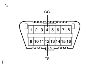
*a Front view of DLC3 Using SST, connect terminals TS and CG of the DLC3.
- SST
- 09843-18040
-
Turn the ignition switch to ON.
-
Check that the ABS warning light comes on for several seconds and then blink in the Test Mode pattern.
Tech Tips
If the ABS warning light does not blink, inspect the TS and CG terminal circuit and ABS warning light circuit.
-
Check the ABS sensor.
Tech Tips
Check that the ABS warning light is blinking in the Test Mode pattern before performing the following ABS sensor check.
-
-
Speed Sensor Check
-
Drive the vehicle straight-ahead.
Accelerate the vehicle to a speed of 45 km/h (28 mph) or more for several seconds.
Tech Tips
-
The speed sensor check may not complete if wheelspin occurs.
-
The speed sensor check may not complete if the speed sensor check is started while turning the steering wheel.
Note
After the ABS warning light goes off, if the vehicle speed exceeds 80 km/h (50 mph), a sensor check code will be stored again.
Decelerate or stop the vehicle before the speed reaches 80 km/h (50 mph).
-
-
Check that the ABS warning light goes off.
Tech Tips
-
The ABS warning light goes off when the sensor check has completed.
-
The ABS warning light comes on immediately after a malfunction has been detected during the speed sensor check.
-
-
Stop the vehicle.
Tech Tips
When the sensor check has completed, the ABS warning light goes off while the vehicle is being driven, and blinks in the Test Mode pattern while the vehicle is stopped.
Note
If the sensor checks have not completed, the ABS warning light will blink while the vehicle is being driven and the ABS will not operate.
-
-
End of Sensor Check
-
If the sensor checks have completed, the ABS warning light blinks in the Test Mode pattern when the vehicle is stopped and the ABS warning light goes off while the vehicle is being driven.
Note
If the sensor checks have not completed, the ABS warning light will blink while the vehicle is being driven and the ABS will not operate.
-
-
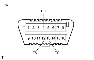
*a Front view of DLC3 Reading Sensor Check DTCs
-
Using SST, connect terminals TC and CG of the DLC3.
- SST
- 09843-18040
-
Count the number of blinks of the ABS warning light.
Tech Tips
-
How to read DTCs:
Diagnostic trouble codes are represented by the number of blinks of a warning light. For example, code 21 would be shown by 2 blinks, a pause of 1.5 seconds, and then 1 blink.
-
If one code is detected:
The light repeats the same code after a pause of 4 seconds.
-
If multiple codes are detected:
The light outputs one code after another with a 2.5-second pause between each code.
When all codes have been output, there is a 4-second pause and then the light begins to output the codes again.
Note
-
If only DTCs other than Test Mode sensor check DTCs are displayed, repair the malfunctions and clear the DTCs.
-
If Test Mode sensor check DTCs and other DTCs are displayed or if only Test Mode sensor check DTCs are displayed, repair the malfunctions, clear the DTCs, and perform Test Mode inspection again.
Tech Tips
-
If more than 1 malfunction is detected at the same time, the lowest numbered code will be displayed first.
-
See "Sensor Check DTCs".
-
-
After performing the check, disconnect SST from terminals TS and CG, and TC and CG of the DLC3, and turn the ignition switch off.
-
Turn the ignition switch to ON to cancel Test Mode.
Tech Tips
-
If the ignition switch is not turned off and back to ON after SST is removed from the DLC3, the previous Test Mode will continue.
-
If the ignition switch is turned back to ON with terminals TS and CG connected, the previous Test Mode will continue.
-
-
-
Sensor Check DTCs
ABS Sensor DTC No. Detection Item Trouble Area 71 Low Output Signal of Front Speed Sensor RH
-
Front speed sensor RH
-
Sensor installation
-
Front speed sensor rotor RH (front drive outboard joint shaft assembly RH)
72 Low Output Signal of Front Speed Sensor LH
-
Front speed sensor LH
-
Sensor installation
-
Front speed sensor rotor LH (front drive outboard joint shaft assembly LH)
73 Low Output Signal of Rear Speed Sensor RH
-
Rear speed sensor RH
-
Sensor installation
-
Rear speed sensor rotor RH (rear axle hub and bearing assembly RH)
74 Low Output Signal of Rear Speed Sensor LH
-
Rear speed sensor LH
-
Sensor installation
-
Rear speed sensor rotor LH (rear axle hub and bearing assembly LH)
75 Abnormal Change in Output Signal of Front Speed Sensor RH Front speed sensor rotor RH (front drive outboard joint shaft assembly RH) 76 Abnormal Change in Output Signal of Front Speed Sensor LH Front speed sensor rotor LH (front drive outboard joint shaft assembly LH) 77 Abnormal Change in Output Signal of Rear Speed Sensor RH Rear speed sensor rotor RH (rear axle hub and bearing assembly RH) 78 Abnormal Change in Output Signal of Rear Speed Sensor LH Rear speed sensor rotor LH (rear axle hub and bearing assembly LH) Tech Tips
The DTCs in this table are output only in Test Mode (signal check).
-
-