REAR AXLE BEAM INSTALLATION

PROCEDURE
-
INSTALL REAR AXLE CARRIER BUSHING LH
-
When reusing the rear axle beam assembly:
-
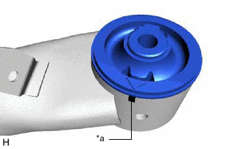
*a Matchmark Align the arrow mark on a new rear axle carrier bushing LH with the matchmark on the rear axle beam assembly and temporarily install the rear axle carrier bushing LH to the rear axle beam assembly.
Note
Be sure to install the rear axle carrier bushing in the same direction as it was before removal. The rear axle carrier bushing has to be installed in a specific direction.
-
-
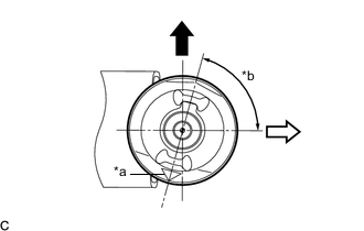
*a Arrow Mark *b 75° 
Upper Side of the Vehicle 
Front of the Vehicle When using a new rear axle beam assembly:
-
Temporarily install a new rear axle carrier bushing LH as shown in the illustration.
Note
Be sure to install the rear axle carrier bushing as shown in the illustration. The rear axle carrier bushing has to be installed in a specific direction.
-
-
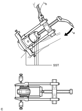
*a Turn *b Hold Using SST, install the rear axle carrier bushing LH to the rear axle beam assembly.
- SST
- 09710-30012 ( 09710-04101 )
- 09950-40011 ( 09951-04020, 09952-04010, 09953-04030, 09954-04020, 09955-04051, 09957-04010, 09958-04011 )
- 09950-60010 ( 09951-00620 )
Note
-
Do not damage the rubber portion when installing the rear axle carrier bushing.
-
Apply grease to the threads and tip of the SST center bolt before use.
-
-
INSTALL REAR AXLE CARRIER BUSHING RH
Tech Tips
Perform the same procedure as for the LH side.
-
TEMPORARILY INSTALL REAR AXLE BEAM ASSEMBLY
-
Slowly jack up the rear axle beam assembly with an engine lifter using 2 wooden blocks and 2 attachments or equivalent tools, and temporarily install the rear axle beam assembly to the body with the 2 bolts (B).
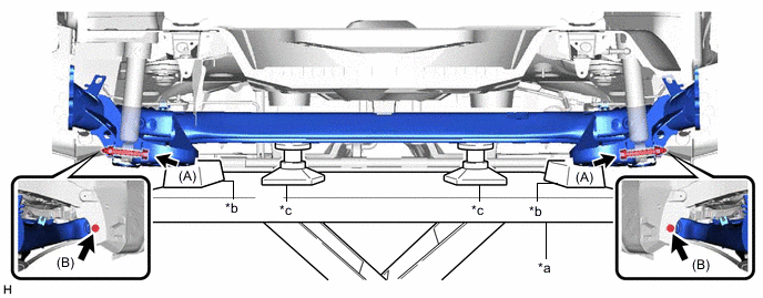
*a Engine Lifter *b Wooden Block *c Attachment - - CAUTION:
Make sure to secure the rear axle beam assembly to prevent it from dropping.
-
Temporarily install the rear axle beam assembly to the rear shock absorber assemblies LH and RH with the 2 bolts (A) and 2 nuts.
Note
Because the nuts have their own stoppers, do not turn the nuts. Tighten the bolts with the nuts secured.
Tech Tips
Insert the bolts with the threaded end facing the outside of the vehicle.
-
-
INSTALL REAR LOWER COIL SPRING INSULATOR LH
-
INSTALL REAR LOWER COIL SPRING INSULATOR RH
Tech Tips
Perform the same procedure as for the LH side.
-
INSTALL REAR UPPER COIL SPRING INSULATOR LH
-
INSTALL REAR UPPER COIL SPRING INSULATOR RH
Tech Tips
Perform the same procedure as for the LH side.
-
INSTALL REAR COIL SPRING LH
-
INSTALL REAR COIL SPRING RH
Tech Tips
Perform the same procedure as for the LH side.
-
INSTALL REAR HEIGHT CONTROL SENSOR SUB-ASSEMBLY (w/ Height Control Sensor)
-
INSTALL REAR AXLE HUB AND BEARING ASSEMBLY LH
-
INSTALL REAR AXLE HUB AND BEARING ASSEMBLY RH
Tech Tips
Perform the same procedure as for the LH side.
-
INSTALL REAR NO. 4 BRAKE TUBE
-
Install the rear No. 4 brake tube to the rear axle beam assembly with the nut.
- Torque:
- 8.5 N*m { 87 kgf*cm, 75 in.*lbf }
-
-
INSTALL REAR NO. 3 BRAKE TUBE
Tech Tips
Perform the same procedure as for the rear No. 4 brake tube.
-
INSTALL REAR BRAKE TUBE FLEXIBLE HOSE (for LH Side)
-
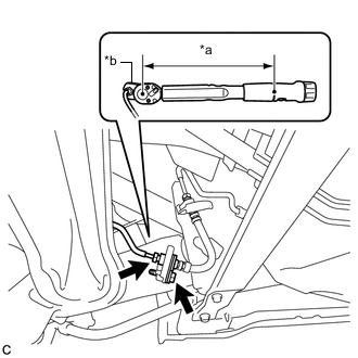
*a Torque Wrench Fulcrum Length *b Union Nut Wrench Install the rear brake tube flexible hose with the bolt.
- Torque:
- 19 N*m { 194 kgf*cm, 14 ft.*lbf }
-
Using a union nut wrench, connect the rear brake tube flexible hose to the rear No. 4 brake tube.
- Torque:
- Specified tightening torque
- 15.2 N*m { 155 kgf*cm, 11 ft.*lbf }
Note
-
Do not kink or damage the brake line.
-
Do not allow any foreign matter such as dirt or dust to enter the brake line from the connecting parts.
Tech Tips
-
Calculate the torque wrench reading when changing the fulcrum length of the torque wrench.
-
When using a union nut wrench (fulcrum length of 22 mm (0.866 in.)) + torque wrench (fulcrum length of 162 mm (6.38 in.)):
13.38 N*m (136 kgf*cm, 10 ft.*lbf)
-
-
INSTALL REAR BRAKE TUBE FLEXIBLE HOSE (for RH Side)
-
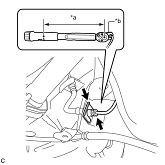
*a Torque Wrench Fulcrum Length *b Union Nut Wrench Install the rear brake tube flexible hose with a new clip.
Note
Install the clip as far as it will go.
-
Using a union nut wrench, connect the rear brake tube flexible hose to the rear No. 3 brake tube.
- Torque:
- Specified tightening torque
- 15.2 N*m { 155 kgf*cm, 11 ft.*lbf }
Note
-
Do not kink or damage the brake line.
-
Do not allow any foreign matter such as dirt or dust to enter the brake line from the connecting parts.
Tech Tips
-
Calculate the torque wrench reading when changing the fulcrum length of the torque wrench.
-
When using a union nut wrench (fulcrum length of 22 mm (0.866 in.)) + torque wrench (fulcrum length of 162 mm (6.38 in.)):
13.38 N*m (136 kgf*cm, 10 ft.*lbf)
-
-
INSTALL REAR DISC
-
Install the 2 rear discs.
-
-
INSTALL REAR DISC BRAKE CALIPER ASSEMBLY LH
-
Install the rear disc brake caliper assembly LH with the rear flexible hose LH with the 2 bolts.
- Torque:
- 72 N*m { 734 kgf*cm, 53 ft.*lbf }
-
Connect the rear flexible hose LH to the rear axle beam assembly with a new clip.
Note
Install the clip as far as it will go.
-
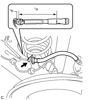
*a Torque Wrench Fulcrum Length *b Union Nut Wrench Using a union nut wrench, connect the rear No. 4 brake tube to the rear flexible hose LH while holding the rear flexible hose LH with a wrench.
- Torque:
- Specified tightening torque
- 15.2 N*m { 155 kgf*cm, 11 ft.*lbf }
Note
-
Do not kink or damage the brake line.
-
Do not allow any foreign matter such as dirt or dust to enter the brake line from the connecting parts.
Tech Tips
-
Calculate the torque wrench reading when changing the fulcrum length of the torque wrench.
-
When using a union nut wrench (fulcrum length of 22 mm (0.866 in.)) + torque wrench (fulcrum length of 162 mm (6.38 in.)):
13.38 N*m (136 kgf*cm, 10 ft.*lbf)
-
-
INSTALL REAR DISC BRAKE CALIPER ASSEMBLY RH
Tech Tips
Perform the same procedure as for the LH side.
-
INSTALL NO. 3 PARKING BRAKE CABLE ASSEMBLY
-
Install the No. 3 parking brake cable assembly to the rear axle beam assembly with the bolt.
- Torque:
- 6.0 N*m { 61 kgf*cm, 53 in.*lbf }
-
Connect No. 3 parking brake cable assembly.
-
-
INSTALL NO. 2 PARKING BRAKE CABLE ASSEMBLY
Tech Tips
Perform the same procedure as for the No. 3 parking brake cable assembly.
-
INSTALL SKID CONTROL SENSOR WIRE LH
-
INSTALL SKID CONTROL SENSOR WIRE RH
Tech Tips
Perform the same procedure as for the LH side.
-
INSTALL REAR FLOOR SIDE MEMBER BRACE SUB-ASSEMBLY
-
Install the rear floor side member brace sub-assembly with the 4 bolts.
- Torque:
- 54 N*m { 551 kgf*cm, 40 ft.*lbf }
-
-
INSTALL REAR FLOOR SIDE MEMBER COVER LH (w/ Cover)
-
Install the rear floor side member cover LH with the 2 bolts and nut.
-
-
INSTALL REAR FLOOR SIDE MEMBER COVER RH (w/ Cover)
-
Install the rear floor side member cover RH with the 2 bolts and nut.
-
-
ADJUST PARKING BRAKE
-
INSTALL UPPER CONSOLE PANEL SUB-ASSEMBLY
for Hatchback, Wagon: Click here
for Sedan: Click here
-
FILL RESERVOIR WITH BRAKE FLUID
-
BLEED BRAKE LINE
-
INSTALL REAR WHEELS
- Torque:
- 103 N*m { 1050 kgf*cm, 76 ft.*lbf }
-
STABILIZE SUSPENSION
-
INSTALL REAR AXLE BEAM ASSEMBLY
-
INSTALL REAR WHEEL HOUSE LINER LH (w/ Wheel House Liner)
-
INSTALL REAR WHEEL HOUSE LINER RH (w/ Wheel House Liner)
Tech Tips
Perform the same procedure as for the LH side.
-
INSPECT REAR WHEEL ALIGNMENT
-
CHECK FOR SPEED SENSOR SIGNAL
w/o VSC: Click here
w/ VSC: Click here