REAR TRAILING ARM REMOVAL
CAUTION / NOTICE / HINT
Tech Tips
-
Use the same procedure for the RH side and LH side.
-
The procedure listed below is for the LH side.
PROCEDURE
-
REMOVE REAR WHEEL
-
REMOVE REAR SUSPENSION ARM COVER
-
REMOVE REAR FLOOR SIDE MEMBER COVER LH (for LH Side)
-
REMOVE REAR FLOOR SIDE MEMBER COVER RH (for RH Side)
-
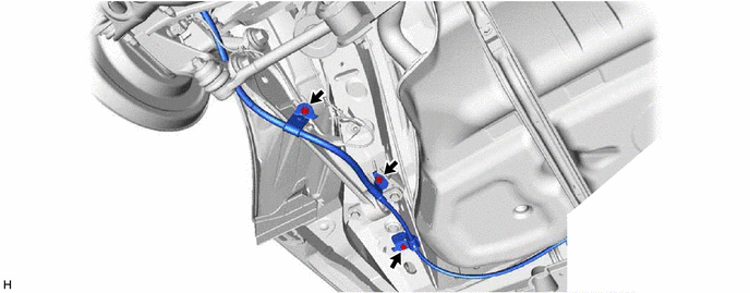
SEPARATE NO. 3 PARKING BRAKE CABLE ASSEMBLY
-
Remove the 3 bolts and separate the No. 3 parking brake cable assembly.
-
-
SEPARATE SKID CONTROL SENSOR WIRE
-
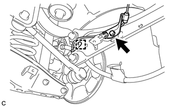
Remove the bolt and disengage the clamp to separate the skid control sensor wire from the rear trailing arm assembly.
-
-
SEPARATE REAR NO. 1 SUSPENSION ARM ASSEMBLY
-
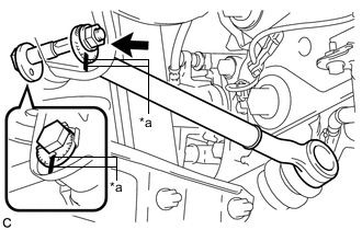
*a Matchmark Place matchmarks on the rear No. 1 suspension camber adjust cam, rear suspension toe adjust cam sub-assembly and rear suspension member sub-assembly.
-
Remove the nut, rear No. 1 suspension camber adjust cam and rear suspension toe adjust cam sub-assembly.
Note
Hold the rear suspension toe adjust cam sub-assembly while rotating the nut.
-
Separate the rear No. 1 suspension arm assembly from the rear suspension member sub-assembly.
-
-
REMOVE REAR TRAILING ARM ASSEMBLY
-
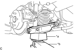
*a Wooden Block *b Jack Using a jack and wooden block, keep the rear No. 2 suspension arm assembly level.
CAUTION:
Do not jack up the rear No. 2 suspension arm assembly too high as the vehicle may fall.
Note
-
When jacking up the rear No. 2 suspension arm assembly, be sure to jack it up slowly.
-
Make sure to perform this operation with the vehicle kept as low as possible.
-
-
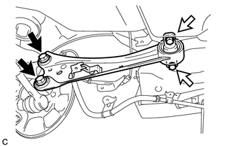

Bolt (A) 
Bolt (B) Remove the 2 bolts (A), 2 bolts (B) and rear trailing arm assembly.
-