REAR LOWER ARM REMOVAL

CAUTION / NOTICE / HINT
Tech Tips
-
Use the same procedure for the RH side and LH side.
-
The procedure listed below is for the LH side.
PROCEDURE
-
REMOVE REAR WHEEL
-
REMOVE REAR SUSPENSION ARM COVER
-
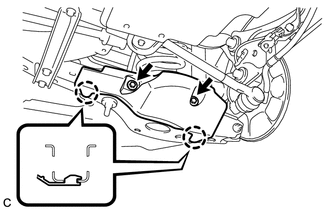
Remove the 2 bolts and disengage the 2 claws to remove the rear suspension arm cover from the rear No. 2 suspension arm assembly.
-
-
REMOVE REAR FLOOR SIDE MEMBER COVER LH (for LH Side)
-
REMOVE REAR FLOOR SIDE MEMBER COVER RH (for RH Side)
-
REMOVE REAR NO. 1 SUSPENSION ARM ASSEMBLY
-
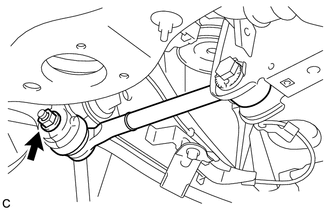
Remove the nut.
-
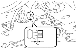
*a 1 mm or more Install 2 spacers (SST spacer B) as shown in the illustration.
- SST
- 09960-20010 ( 09961-02060 )
Note
As SST may be damaged, make sure that the clearance between the rear axle assembly and spacers is 1 mm (0.0394 in.) or more.
-
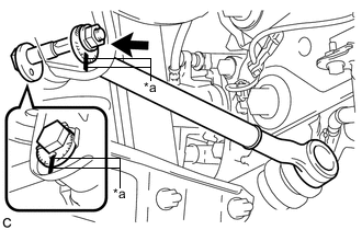
Using SST, separate the rear No. 1 suspension arm assembly from the rear axle assembly as shown in the illustration.
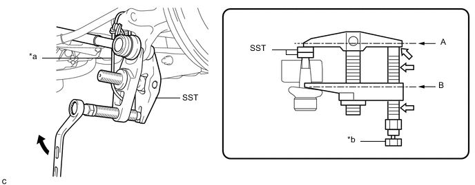
*a Tie string without any slack *b Place wrench here 
Turn 
Molybdenum Grease - SST
- 09960-20010 ( 09961-02010, 09961-02060 )
CAUTION:
Apply molybdenum grease to the threads and end of the SST bolt.
Note
-
Be sure to tighten the string firmly to secure SST to the rear axle assembly to prevent SST from falling off.
-
Install SST so that A and B are parallel.
-
Be sure to place the wrench on the part indicated in the illustration.
-
Do not damage the ball joint dust cover.
-
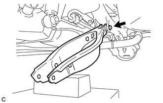
*a Matchmark Place matchmarks on the rear No. 1 suspension camber adjust cam, rear suspension toe adjust cam sub-assembly and rear suspension member sub-assembly.
-
Remove the nut, rear No. 1 suspension camber adjust cam, rear suspension toe adjust cam sub-assembly and rear No. 1 suspension arm assembly.
Note
Hold the rear suspension toe adjust cam sub-assembly while rotating the nut.
-
-
REMOVE REAR HEIGHT CONTROL SENSOR SUB-ASSEMBLY (w/ Height Control Sensor)
-
REMOVE REAR STABILIZER LINK ASSEMBLY
-
REMOVE REAR SUSPENSION MEMBER BRACE
-
REMOVE REAR COIL SPRING
-
REMOVE REAR UPPER COIL SPRING INSULATOR
-
REMOVE REAR LOWER COIL SPRING INSULATOR
-
REMOVE REAR NO. 2 SUSPENSION ARM ASSEMBLY
-
Remove the bolt, nut and rear No. 2 suspension arm assembly from the rear suspension member sub-assembly.
Note
Because the nut has its own stopper, do not turn the nut. Loosen the bolt with the nut secured.
-