FRONT SUSPENSION MEMBER REMOVAL

PROCEDURE
-
PLACE FRONT WHEELS FACING STRAIGHT AHEAD
-
SECURE STEERING WHEEL
-
REMOVE COLUMN HOLE COVER SILENCER SHEET
-
SEPARATE NO. 2 STEERING INTERMEDIATE SHAFT ASSEMBLY
-
SEPARATE NO. 1 STEERING COLUMN HOLE COVER SUB-ASSEMBLY
-
REMOVE FRONT WHEELS
-
REMOVE FRONT LOWER BUMPER ABSORBER
-
REMOVE NO. 1 ENGINE UNDER COVER
-
REMOVE CENTER NO. 4 ENGINE UNDER COVER (w/ Cover)
-
REMOVE FRONT NO. 3 ENGINE UNDER COVER (for Full Cover Type)
-
REMOVE REAR ENGINE UNDER COVER LH
-
REMOVE REAR ENGINE UNDER COVER RH
-
SEPARATE FRONT STABILIZER LINK ASSEMBLY LH
-
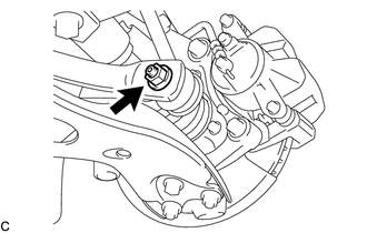
Remove the nut and separate the front stabilizer link assembly LH from the front stabilizer bar.
Note
Do not damage the boot of the ball joint.
Tech Tips
If the ball joint turns together with the nut, use a 6 mm hexagon wrench to hold the stud bolt.
-
-
SEPARATE FRONT STABILIZER LINK ASSEMBLY RH
Tech Tips
Perform the same procedure as for the LH side.
-
SEPARATE TIE ROD END SUB-ASSEMBLY LH
-
SEPARATE TIE ROD END SUB-ASSEMBLY RH
Tech Tips
Perform the same procedure as for the LH side.
-
SEPARATE FRONT LOWER NO. 1 SUSPENSION ARM SUB-ASSEMBLY LH
-
SEPARATE FRONT LOWER NO. 1 SUSPENSION ARM SUB-ASSEMBLY RH
Tech Tips
Perform the same procedure as for the LH side.
-
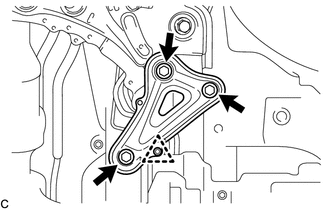
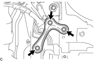
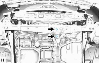
REMOVE FRONT ENGINE MOUNTING BRACKET LOWER REINFORCEMENT (w/ Reinforcement)
-
Remove the 2 bolts and front engine mounting bracket lower reinforcement.
-
-
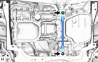
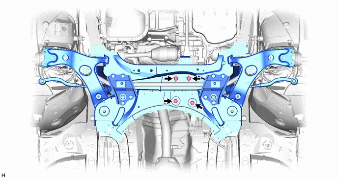
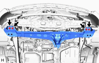
REMOVE FRONT SUSPENSION MEMBER REINFORCEMENT LH
-
Remove the 4 bolts and front suspension member reinforcement LH.
-
-
REMOVE FRONT SUSPENSION MEMBER REINFORCEMENT RH
Tech Tips
Perform the same procedure as for the LH side.
-
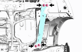
REMOVE FRONT SUSPENSION MEMBER REAR BRACE LH
-
Type A:
-
Remove the 3 bolts, clip and front suspension member rear brace LH.
-
-
Type B:
-
Remove the 3 bolts and front suspension member rear brace LH.
-
-
-
REMOVE FRONT SUSPENSION MEMBER REAR BRACE RH
Tech Tips
Perform the same procedure as for the LH side.
-
REMOVE FRONT SUSPENSION CROSSMEMBER SUB-ASSEMBLY
-
for 1ZR-FE, 1ZR-FAE, 2ZR-FE, 1AD-FTV:
-
Remove the 2 bolts and 2 wiring harness clamp brackets from the front suspension crossmember sub-assembly.
-
-
Remove the 2 bolts and 2 nuts, and separate the rear engine mounting insulator from the front suspension crossmember sub-assembly.
-
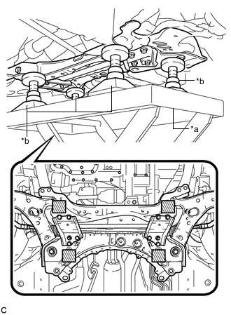
*a Engine Lifter *b Attachment 
Attachment Placement Location Support the front suspension crossmember sub-assembly with an engine lifter using 4 attachments or equivalent tools as shown in the illustration.
CAUTION:
-
The front suspension crossmember sub-assembly is a heavy component. Make sure that it is supported securely.
-
Make sure to secure the front suspension crossmember sub-assembly to prevent it from dropping.
Note
Use the attachments to keep the front suspension crossmember sub-assembly level.
-
-
Remove the 2 bolts and front suspension crossmember sub-assembly.
-
Slowly lower the front suspension crossmember sub-assembly.
Note
When lowering the front suspension crossmember sub-assembly, be careful not to damage the vehicle body or other components installed on the vehicle.
-
-
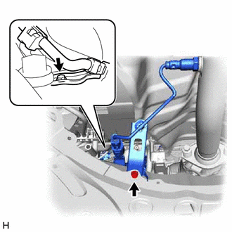
REMOVE FRONT CROSS MEMBER SUB-ASSEMBLY
-
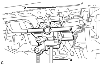
*a Jack *b Wooden Block Using a jack and wooden blocks, support the engine and transaxle assembly.
-
Remove the 2 bolts and separate the front engine mounting insulator from the front cross member sub-assembly.
-
Remove the 4 bolts and front cross member sub-assembly.
-
-
REMOVE STEERING LINK ASSEMBLY
-
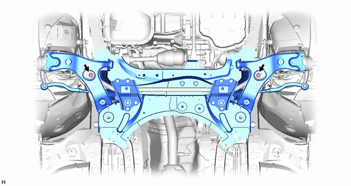
REMOVE FRONT LOWER NO. 1 SUSPENSION ARM SUB-ASSEMBLY LH
-
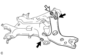

Bolt 
Nut Remove the 2 bolts, nut and front lower No. 1 suspension arm sub-assembly LH from the front suspension crossmember sub-assembly.
Note
Because the nut has its own stopper, do not turn the nut. Loosen the bolt with the nut secured.
-
-
REMOVE FRONT LOWER NO. 1 SUSPENSION ARM SUB-ASSEMBLY RH
Tech Tips
Perform the same procedure as for the LH side.
-
REMOVE FRONT SUSPENSION MEMBER BRACE
-
REMOVE FRONT STABILIZER BAR
-
Remove the front stabilizer bar with 2 front stabilizer bar bushings from the front suspension crossmember sub-assembly.
-