FRONT LOWER BALL JOINT REMOVAL

CAUTION / NOTICE / HINT
Tech Tips
-
Use the same procedure for the RH side and LH side.
-
The procedure listed below is for the LH side.
PROCEDURE
-
REMOVE FRONT AXLE ASSEMBLY
-
REMOVE FRONT LOWER BALL JOINT ASSEMBLY
-
Secure the front axle assembly in a vise using aluminum plates.
Note
Do not overtighten the vise.
-
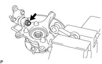
Remove the cotter pin and nut.
-
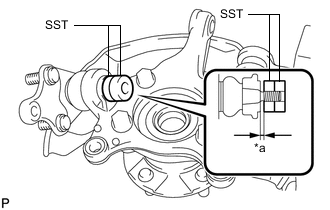
*a 1 mm (0.0394 in.) Install SST to the front lower ball joint assembly as shown in the illustration.
- SST
- 09960-20010 ( 09961-02050, 09961-02050 )
Note
Check that the clearance measurement between SST and the front axle assembly is 1 mm (0.0394 in.).
-

*a Molybdenum grease application area *b Place wrench here *c Center Nut Using SST, remove the front lower ball joint assembly from the front axle assembly as shown in the illustration.
- SST
- 09960-20010 ( 09961-02010, 09961-02050, 09961-02050 )
CAUTION:
Apply molybdenum grease to the threads and end of the SST bolt.
Note
-
Install SST with the center nut so that A and B shown in the illustration are parallel. Otherwise, the front lower ball joint dust cover may be damaged.
-
Be sure to place a wrench on the part indicated in the illustration.
-
Do not damage the front lower ball joint dust cover.
-
Do not damage the steering knuckle.
-
Do not damage the front disc brake dust cover.
-