FRONT LOWER SUSPENSION ARM(for LH Side) INSTALLATION

CAUTION / NOTICE / HINT
Tech Tips
For models with manual transaxle, the front lower No. 1 suspension arm sub-assembly LH can be installed without removing the front suspension crossmember sub-assembly.
PROCEDURE
-
TEMPORARILY TIGHTEN FRONT LOWER NO. 1 SUSPENSION ARM SUB-ASSEMBLY LH (for Multi-Mode Manual Transaxle)
-
TEMPORARILY TIGHTEN FRONT LOWER NO. 1 SUSPENSION ARM SUB-ASSEMBLY LH (for CVT)
-
TEMPORARILY TIGHTEN FRONT LOWER NO. 1 SUSPENSION ARM SUB-ASSEMBLY LH (for Manual Transaxle)
-
Temporarily install the front lower No. 1 suspension arm sub-assembly LH to the front suspension crossmember sub-assembly with the 2 bolts and nut.
Note
Because the nut has its own stopper, do not turn the nut. Tighten the bolt with the nut secured.
-
-
CONNECT FRONT LOWER NO. 1 SUSPENSION ARM SUB-ASSEMBLY LH (for Manual Transaxle)
-
INSTALL FRONT WHEEL
- Torque:
- 103 N*m { 1050 kgf*cm, 76 ft.*lbf }
-
STABILIZE SUSPENSION
-
FULLY TIGHTEN FRONT LOWER NO. 1 SUSPENSION ARM SUB-ASSEMBLY LH
-
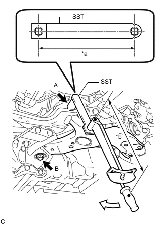
*a Length of SST 200 mm (7.87 in.) *b Length of Torque Wrench 425 mm (1.39 ft.) 
Turn Using SST, fully tighten the bolt A.
- SST
- 09961-01270
- Torque:
- without SST [Torque (N*m(kgf*cm, ft.*lbf))]
- 233 N*m { 2376 kgf*cm, 172 ft.*lbf }
- with SST [Reading of Torque wrench (N*m(kgf*cm, ft.*lbf))]
- 158 N*m { 1611 kgf*cm, 117 ft.*lbf }
Tech Tips
-
This torque value is effective when SST is parallel to the torque wrench.
-
The "with SST" torque value is effective when using SST with a fulcrum length of 200 mm (7.87 in.).
-
The "with SST" torque value is effective when using a torque wrench with a fulcrum length of 425 mm (1.39 ft.).
-
If using a torque wrench with a different length, or connecting the torque wrench and SST at an angle, refer to the alternate torque values.
-
Fully tighten the bolt B.
- Torque:
- 214 N*m { 2182 kgf*cm, 158 ft.*lbf }
Note
Because the nut has its own stopper, do not turn the nut. Tighten the bolt with the nut secured.
-
-
INSTALL NO. 1 ENGINE UNDER COVER
-
INSPECT AND ADJUST FRONT WHEEL ALIGNMENT