FRONT SHOCK ABSORBER REMOVAL

CAUTION / NOTICE / HINT
Tech Tips
-
Use the same procedure for the RH side and LH side.
-
The procedure listed below is for the LH side.
PROCEDURE
-
REMOVE WINDSHIELD WIPER MOTOR AND LINK ASSEMBLY
-
REMOVE WATER GUARD PLATE LH (for LHD)
-
REMOVE WATER GUARD PLATE LH (for RHD)
-
REMOVE NO. 2 HEATER AIR DUCT SPLASH SHIELD SEAL (for LHD)
-
REMOVE NO. 2 HEATER AIR DUCT SPLASH SHIELD SEAL (for RHD)
-
SEPARATE DIFFERENTIAL PRESSURE SENSOR ASSEMBLY (for 1AD-FTV LHD)
-
REMOVE OUTER COWL TOP PANEL (for LHD)
-
REMOVE OUTER COWL TOP PANEL (for RHD)
-
REMOVE FRONT WHEEL
-
SEPARATE FRONT STABILIZER LINK ASSEMBLY
-
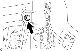
Remove the nut and separate the front stabilizer link assembly from the front shock absorber assembly.
Note
Do not damage the boot of the ball joint.
Tech Tips
If the ball joint turns together with the nut, use a 6 mm hexagon wrench to hold the stud bolt.
-
-
SEPARATE FRONT SPEED SENSOR
-
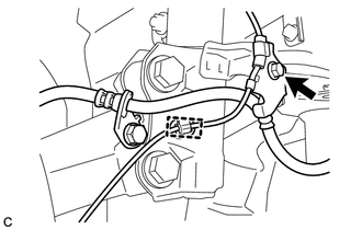
Remove the bolt, disengage the clamp and separate the front speed sensor and front flexible hose from the front shock absorber assembly.
Note
Be sure to separate the front speed sensor from the front shock absorber assembly completely.
-
-
REMOVE FRONT SUSPENSION SUPPORT DUST COVER
-
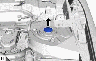
Remove the front suspension support dust cover.
-
-
REMOVE FRONT SHOCK ABSORBER WITH COIL SPRING
-
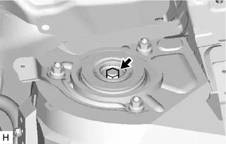
Loosen the front support to front shock absorber nut.
Note
-
Do not remove the front support to front shock absorber nut.
-
Loosen the front support to front shock absorber nut only when the front shock absorber with coil spring needs to be disassembled.
-
-
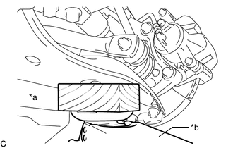
*a Wooden Block *b Jack Support the front lower No. 1 suspension arm sub-assembly using a jack and wooden block.
-
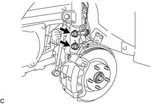
Remove the 2 bolts and 2 nuts, and separate the front shock absorber with coil spring (lower side) from the steering knuckle.
Note
When removing the nuts, keep the bolts from rotating.
-
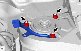
Remove the 3 nuts, front fender apron rear extension and front shock absorber with coil spring.
Note
Make sure that the front speed sensor is completely separated from the front shock absorber with coil spring.
-
-
REMOVE FRONT SUPPORT TO FRONT SHOCK ABSORBER NUT
-
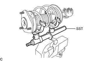
Secure SST in a vise.
- SST
- 09727-30021 ( 09727-00010, 09727-00021, 09727-00031 )
-
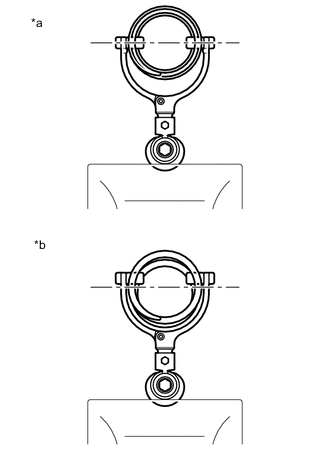
*a Correct *b Incorrect Attach the arms of SST to the diameter of the front coil spring.
CAUTION:
-
Make sure that the front coil spring is installed so that the distance between the upper and lower arms of SST is at the maximum.
-
Make sure that the claws of the arms are securely attached.
-
-
Using SST, compress the front coil spring.
CAUTION:
-
If the front coil spring bends during compression, immediately stop compression and reinstall SST.
-
Do not excessively compress the front coil spring so that the coils contact each other.
-
Do not use an impact wrench. It will damage SST.
-
-
Confirm that the front coil spring is free and remove the front support to front shock absorber nut.
CAUTION:
Do not remove the front support to front shock absorber nut when the front coil spring is not free.
-
-
REMOVE FRONT SUSPENSION SUPPORT SUB-ASSEMBLY
-
REMOVE FRONT SUSPENSION SUPPORT DUST SEAL
-
REMOVE FRONT UPPER COIL SPRING SEAT
-
REMOVE FRONT UPPER COIL SPRING INSULATOR
-
REMOVE FRONT COIL SPRING
-
REMOVE FRONT SPRING BUMPER
-
REMOVE FRONT LOWER COIL SPRING INSULATOR
-
REMOVE FRONT SHOCK ABSORBER ASSEMBLY