FRONT AXLE HUB ON-VEHICLE INSPECTION
CAUTION / NOTICE / HINT
Tech Tips
-
Use the same procedure for the RH side and LH side.
-
The procedure listed below is for the LH side.
PROCEDURE
-
REMOVE FRONT WHEEL
-
SEPARATE FRONT DISC BRAKE CALIPER ASSEMBLY
-
REMOVE FRONT DISC
-
INSPECT FRONT AXLE HUB BEARING LOOSENESS
-
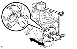
Using a dial indicator, check for looseness near the center of the front axle hub sub-assembly.
Maximum Looseness 0.05 mm (0.00196 in.) Note
-
Ensure that the dial indicator is set perpendicular to the measurement surface.
-
Keep the magnet of the dial indicator away from the front speed sensor.
Tech Tips
If the looseness exceeds the maximum, replace the front axle hub sub-assembly.
-
-
-
INSPECT FRONT AXLE HUB RUNOUT
-
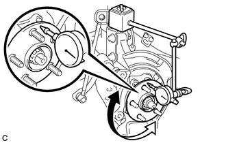
Using a dial indicator, check for runout on the surface of the front axle hub sub-assembly outside the front axle hub bolts.
Maximum Runout 0.05 mm (0.00196 in.) Note
-
Ensure that the dial indicator is set perpendicular to the measurement surface.
-
Make sure to set the tip of the dial indicator towards the outside of the front axle hub bolts.
-
Keep the magnet of the dial indicator away from the front speed sensor.
Tech Tips
If the runout exceeds the maximum, replace the front axle hub sub-assembly.
-
-
-
INSTALL FRONT DISC
-
INSTALL FRONT DISC BRAKE CALIPER ASSEMBLY
-
INSTALL FRONT WHEEL
- Torque:
- 103 N*m { 1050 kgf*cm, 76 ft.*lbf }