REAR WHEEL ALIGNMENT(for Double Wishbone Type Suspension) ADJUSTMENT
PROCEDURE
-
INSPECT TIRES
-
MEASURE VEHICLE HEIGHT
-
INSPECT CAMBER
Note
Inspect while the vehicle is unloaded.
-
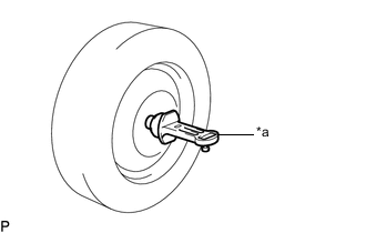
*a Camber-caster-kingpin Gauge Install a camber-caster-kingpin gauge.
-
Inspect the camber.
Camber (Unloaded Vehicle) - Engine Tire Size Camber Inclination Right-left Difference for Hatchback 1AD-FTV 205/55R16 -1°05' +/- 0°45' (-1.08° +/-0.75°) 0°45' (0.75°) or less 225/45R17 -1°05' +/- 0°45' (-1.08° +/-0.75°) 1ZR-FAE 195/65R15 -1°00' +/- 0°45' (-1.00° +/-0.75°)
-0°40' +/- 0°45' (-0.67° +/-0.75°)*1
205/55R16 -1°00' +/- 0°45' (-1.00° +/-0.75°)
-0°40' +/- 0°45' (-0.67° +/-0.75°)*1
225/45R17 -1°00' +/- 0°45' (-1.00° +/-0.75°) for Wagon 1AD-FTV 205/55R16
225/45R17
-1°06' +/- 0°45' (-1.10° +/-0.75°) 1ZR-FAE 195/65R15
205/55R16
225/45R17
-1°00' +/- 0°45' (-1.00° +/-0.75°) *1: for Rough Road Package
Tech Tips
Camber is not adjustable. If the measurement is not within the specified range, inspect the suspension parts for damage and/or wear, and replace them if necessary.
-
-
INSPECT TOE-IN
Note
Inspect while the vehicle is unloaded.
-
Bounce the vehicle up and down at the corners to stabilize the suspension.
-
Release the parking brake and move the shift lever to N (for CVT).
-
Release the parking brake and move the shift lever to neutral (for Manual Transaxle).
-
Push the vehicle straight ahead approximately 5 m (16.4 ft.). (Step A)
-
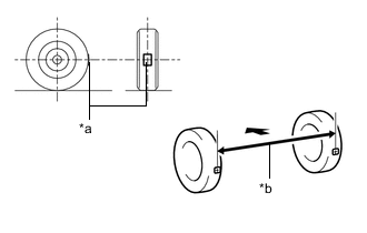
*a Tread Center Mark *b Dimension B 
Front of the Vehicle Put tread center marks on the rearmost points of the rear wheels and measure the distance between the marks (dimension B).
-
Slowly push the vehicle straight ahead to cause the rear wheels to rotate 180°. Use the rear tire valve as a reference point.
Tech Tips
Do not allow the wheels to rotate more than 180°. If the wheels rotate more than 180°, perform the procedure from step A again.
-
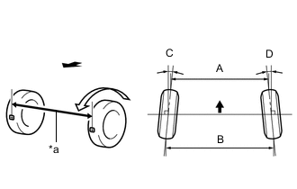
*a Dimension A Front of the Vehicle Measure the distance between the tread center marks on the front of the rear wheels (dimension A).
Toe-in (Unloaded Vehicle) Engine Specified Condition Right-left Difference 1AD-FTV C + D: 0°11' +/- 0°10' (0.18° +/- 0.17°) 0°45' (0.75°) or less B - A: 2.1 +/- 2.0 mm (0.0827 +/- 0.0787 in.) 1.0 mm (0.0394 in.) or less 1ZR-FAE C + D: 0°09' +/- 0°10' (0.15° +/- 0.17°)
C + D: 0°02' +/- 0°10' (0.03° +/- 0.17°)*1
0°45' (0.75°) or less B - A: 1.8 +/- 2.0 mm (0.0709 +/- 0.0787 in.)
B - A: 0.5 +/- 2.0 mm (0.0197 +/- 0.0787 in.)*1
1.0 mm (0.0394 in.) or less *1: for Rough Road Package
Tech Tips
Measure "B - A" only when "C + D" cannot be measured.
If the toe-in is not within the specified range, adjust it at the rear No. 1 suspension arms.
-
-
ADJUST TOE-IN
-
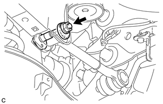
Loosen the nut of the rear No. 1 suspension arm assembly (on the rear suspension member side).
Note
Hold the rear suspension toe adjust cam sub-assembly while rotating the nut.
-
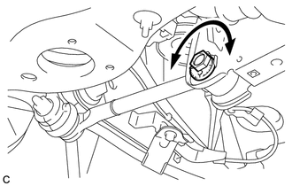
Rotate the rear suspension toe adjust cam sub-assembly to adjust the toe-in.
Toe-in (Unloaded Vehicle) Engine Specified Condition Right-left Difference 1AD-FTV C + D: 0°11' +/- 0°10' (0.18° +/- 0.17°) 0°45' (0.75°) or less B - A: 2.1 +/- 2.0 mm (0.0827 +/- 0.0787 in.) 1.0 mm (0.0394 in.) or less 1ZR-FAE C + D: 0°09' +/- 0°10' (0.15° +/- 0.17°)
C + D: 0°02' +/- 0°10' (0.03° +/- 0.17°)*1
0°45' (0.75°) or less B - A: 1.8 +/- 2.0 mm (0.0709 +/- 0.0787 in.)
B - A: 0.5 +/- 2.0 mm (0.0197 +/- 0.0787 in.)*1
1.0 mm (0.0394 in.) or less *1: for Rough Road Package
Tech Tips
Rotating the rear suspension toe adjust cam sub-assembly by one notch changes the toe by approximately 3.5 mm (0.138 in.).
-
Tighten the nut of the rear No. 1 suspension arm assembly (on the rear suspension member side).
- Torque:
- 100 N*m { 1020 kgf*cm, 74 ft.*lbf }
Note
-
Hold the rear suspension toe adjust cam sub-assembly while rotating the nut.
-
Make sure that all tires of the vehicle are on the ground and the vehicle is unloaded.
-