FRONT DRIVE SHAFT ASSEMBLY(for 1ZR-FAE) REASSEMBLY

PROCEDURE
-
INSTALL FRONT DRIVE SHAFT DUST COVER
-
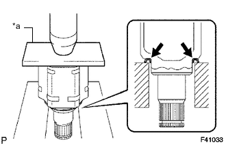
*a Steel Plate Using a steel plate and a press, install a new front drive shaft dust cover.
Note
-
The dust cover should be completely installed.
-
Be careful not to damage the front drive shaft dust cover.
-
-
-
INSTALL FRONT AXLE OUTBOARD JOINT BOOT (for LH Side)
-
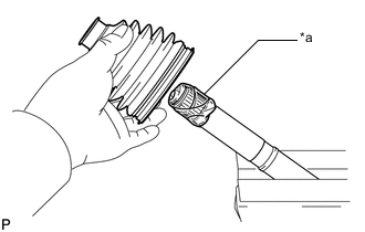
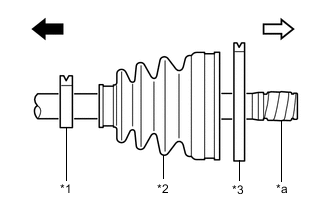
*a Protective Tape Wrap the splines of the front drive outboard joint shaft assembly with protective tape to prevent the boot from being damaged.
-
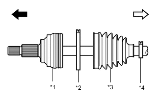
*1 Front Drive Outboard Joint Shaft Assembly *2 Front No. 2 Axle Outboard Joint Boot Clamp LH *3 Front Axle Outboard Joint Boot *4 Front Axle Outboard Joint Boot Clamp LH 
Outboard Joint Side 
Inboard Joint Side Install new parts onto the front drive outboard joint shaft assembly in the following order:
-
Front No. 2 axle outboard joint boot clamp LH
-
Front axle outboard joint boot
-
Front axle outboard joint boot clamp LH
-
-
Pack the joint portion of the front drive outboard joint shaft assembly and front axle outboard joint boot with grease.
Standard Grease Capacity 149.5 to 159.5 g (5.28 to 5.62 oz) -
Install the front axle outboard joint boot into the front drive outboard joint shaft assembly groove.
Note
-
Do not allow grease to adhere to the boot clamp track of the outboard joint boot.
-
Keep the inside of the outboard joint boot free of foreign matter.
-
-
-
INSTALL FRONT NO. 2 AXLE OUTBOARD JOINT BOOT CLAMP LH
-
Hold the drive shaft in a vise between aluminum plates.
Note
Do not overtighten the vise.
-
Install the front No. 2 axle outboard joint boot clamp LH onto the front axle outboard joint boot.
-
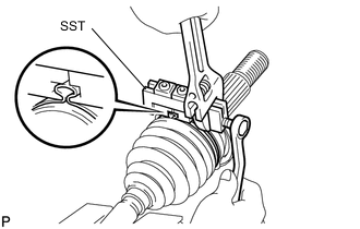
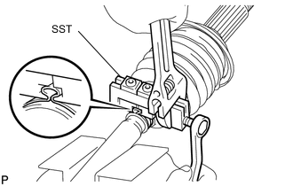
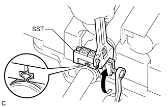
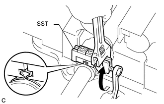
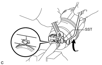
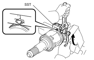
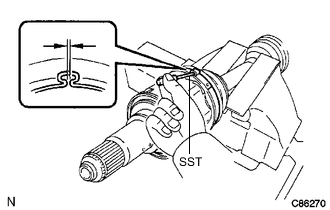
Place SST onto the front No. 2 axle outboard joint boot clamp LH, press it against the boot and slightly tighten SST.
- SST
- 09521-24010
-
Tighten SST so that the front No. 2 axle outboard joint boot clamp LH is pinched.
Note
Do not overtighten SST.
-
Remove SST.
-
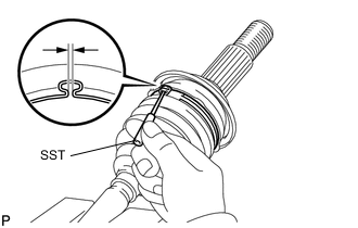
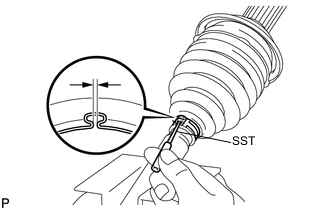
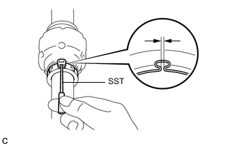
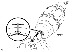
Using SST, measure the clearance of the front No. 2 axle outboard joint boot clamp LH.
- SST
- 09240-00020
Clearance 0.5 to 1.5 mm (0.0197 to 0.0590 in.) If the clearance is outside the specified range, retighten SST.
-
-
INSTALL FRONT AXLE OUTBOARD JOINT BOOT CLAMP LH
-
Install the front axle outboard joint boot clamp LH onto the front axle outboard joint boot.
-
Place SST onto the front axle outboard joint boot clamp LH, press it against the boot and slightly tighten SST.
- SST
- 09521-24010
-
Tighten SST so that the front axle outboard joint boot clamp LH is pinched.
Note
Do not overtighten SST.
-
Remove SST.
-
Using SST, measure the clearance of the front axle outboard joint boot clamp LH.
- SST
- 09240-00020
Clearance 0.5 to 1.5 mm (0.0197 to 0.0590 in.) If the clearance is outside the specified range, retighten SST.
-
-
INSTALL FRONT DRIVE SHAFT DAMPER LH (w/ Drive Shaft Damper)
-
Install the front drive shaft damper LH onto the front drive outboard joint shaft assembly.
-
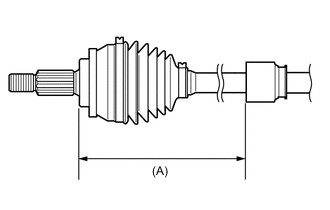
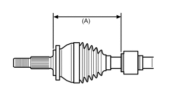
Set the dimension as specified below.
Dimension (A) 161 to 165 mm (6.34 to 6.49 in.) -
Hold the drive shaft in a vise between aluminum plates.
Note
Do not overtighten the vise.
-
Install a new front drive shaft damper clamp onto the front drive shaft damper LH.
Note
Be sure to install the clamp in the correct position.
-
Place SST onto the front drive shaft damper clamp, press it against the front drive shaft damper LH and slightly tighten SST.
- SST
- 09521-24010
-
Tighten SST so that the front drive shaft damper clamp is pinched.
Note
Do not overtighten SST.
-
Remove SST.
-
Using SST, measure the clearance of the front drive shaft damper clamp.
- SST
- 09240-00020
Clearance 0.5 to 1.5 mm (0.0197 to 0.0590 in.) If the clearance is outside the specified range, retighten SST.
-
-
INSTALL FRONT DRIVE SHAFT DAMPER RH (w/ Drive Shaft Damper)
-
Install the front drive shaft damper RH onto the front drive outboard joint shaft assembly.
-
Set the dimension as specified below.
Dimension (A) 434 to 438 mm (1.424 to 1.436 ft.) -
Hold the drive shaft in a vise between aluminum plates.
Note
Do not overtighten the vise.
-
Install a new front drive shaft damper clamp onto the front drive shaft damper RH.
Note
Be sure to install the clamp in the correct position.
-
Place SST onto the front drive shaft damper clamp, press it against the front drive shaft damper RH and slightly tighten SST.
- SST
- 09521-24010
-
Tighten SST so that the front drive shaft damper clamp is pinched.
Note
Do not overtighten SST.
-
Remove SST.
-
Using SST, measure the clearance of the front drive shaft damper clamp.
- SST
- 09240-00020
Clearance 0.5 to 1.5 mm (0.0197 to 0.0590 in.) If the clearance is outside the specified range, retighten SST.
-
-
INSTALL FRONT DRIVE INBOARD JOINT ASSEMBLY
-
*1 Front Axle Inboard Joint Boot Clamp *2 Front Axle Inboard Joint Boot *3 Front No. 2 Axle Inboard Joint Boot Clamp *a Protective Tape Outboard Joint Side Inboard Joint Side Install new parts onto the front drive outboard joint shaft assembly in the following order:
-
Front axle inboard joint boot clamp
-
Front axle inboard joint boot
-
Front No. 2 axle inboard joint boot clamp
-
-
Hold the drive shaft in a vise between aluminum plates.
Note
Do not overtighten the vise.
-
Remove the protective tape.
-
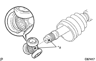
*a Matchmark Align the matchmarks and install the tripod joint onto the front drive outboard joint shaft assembly.
-
Align the matchmarks placed before removal.
-
Using a brass bar and a hammer, install the tripod joint to the front drive outboard joint shaft assembly.
Note
-
Do not tap the rollers.
-
Keep the tripod joint free of foreign matter.
-
-
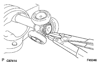
Using a snap ring expander, install a new shaft snap ring to the front drive outboard joint shaft assembly.
-
Pack the front drive inboard joint assembly and front axle inboard boot with grease.
Standard Grease Capacity LH Side 162 to 178 g (5.72 to 6.27 oz) RH Side 155 to 171 g (5.47 to 6.03 oz) -
*a Matchmark Align the matchmarks and install the front drive inboard joint assembly to the front drive outboard joint shaft assembly.
-
-
INSTALL FRONT AXLE INBOARD JOINT BOOT
-
Install the front axle inboard joint boot to the front drive inboard joint assembly.
-
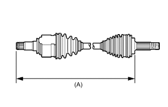
Check whether each drive shaft dimension (A) is within specification.
Dimension (A) Dimension (A) LH Side 589.5 mm (1.93 ft.) RH Side 875.25 mm (2.87 ft.)
-
-
INSTALL FRONT AXLE INBOARD JOINT BOOT CLAMP
-
Hold the drive shaft in a vise between aluminum plates.
Note
Do not overtighten the vise.
-
Install the front axle inboard joint boot clamp onto the front axle inboard joint boot.
-
Place SST onto the front axle inboard joint boot clamp, press it against the boot and slightly tighten SST.
- SST
- 09521-24010
-
Tighten SST so that the front axle inboard joint boot clamp is pinched.
Note
Do not overtighten SST.
-
Remove SST.
-
Using SST, measure the clearance of the front axle inboard joint boot clamp.
- SST
- 09240-00020
Clearance 0.5 to 1.5 mm (0.0197 to 0.0590 in.) If the clearance is outside the specified range, retighten SST.
-
-
INSTALL FRONT NO. 2 AXLE INBOARD JOINT BOOT CLAMP
-
for LH Side:
-
Install the front No. 2 axle inboard joint boot clamp onto the front axle inboard joint boot.
-
Place SST onto the front No. 2 axle inboard joint boot clamp, press it against the boot and slightly tighten SST.
- SST
- 09521-24010
-
Tighten SST so that the front No. 2 axle inboard joint boot clamp is pinched.
Note
Do not overtighten SST.
-
Remove SST.
-
Using SST, measure the clearance of the front No. 2 axle inboard joint boot clamp.
- SST
- 09240-00020
Clearance 0.5 to 1.5 mm (0.0197 to 0.0590 in.) If the clearance is outside the specified range, retighten SST.
-
-
for RH Side:
-
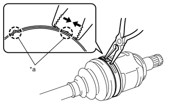
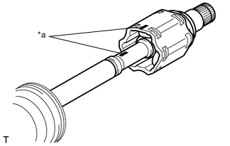
*a Claw Using needle nose pliers, engage the 2 claws to install the front No. 2 axle inboard joint boot clamp.
Note
Be careful not to damage the front axle inboard joint boot.
-
-
-
INSPECT FRONT DRIVE SHAFT ASSEMBLY