SHIFT LEVER(for TMMT Made) INSTALLATION
PROCEDURE
-
INSTALL SHIFT LEVER ASSEMBLY (for LHD)
-
Temporarily install the shift lever assembly to the vehicle body with the 4 bolts.
-
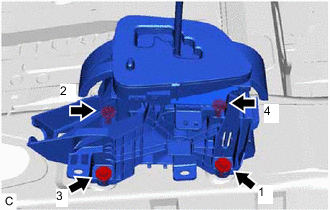
Fully tighten the 4 bolts in the order shown in the illustration.
- Torque:
- 12 N*m { 122 kgf*cm, 9 ft.*lbf }
-
w/o Smart Entry and Start System:
-
Engage the 5 clamps to connect the wire harness to the shift lever assembly.
-
Connect the shift lock control ECU connector.
-
Connect the indicator light wire sub-assembly connector.
-
Connect the transmission control switch connector.
-
-
w/ Smart Entry and Start System:
-
Engage the 5 clamps to connect the wire harness to the shift lever assembly.
-
Connect the shift lock control ECU connector.
-
Connect the indicator light wire sub-assembly connector.
-
Connect the transmission control switch connector.
-
-
-
INSTALL SHIFT LEVER ASSEMBLY (for RHD)
-
Temporarily install the shift lever assembly to the vehicle body with the 4 bolts.
-
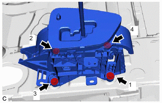
Fully tighten the 4 bolts in the order shown in the illustration.
- Torque:
- 12 N*m { 122 kgf*cm, 9 ft.*lbf }
-
Engage the 5 clamps to connect the wire harness to the shift lever assembly.
-
Connect the shift lock control ECU connector.
-
Connect the indicator light wire sub-assembly connector.
-
Connect the transmission control switch connector.
-
-
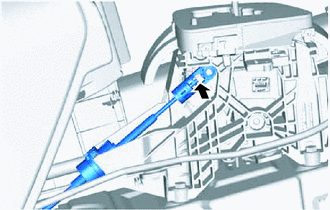
CONNECT TRANSMISSION CONTROL CABLE ASSEMBLY
-
Turn the nut of the transmission control cable assembly approximately 180° counterclockwise. While holding the nut in place, push in the stopper until it clicks twice.
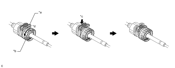
*a Stopper *b Nut *c Push in *d Turn approximately 180° Tech Tips
If the stopper cannot be pushed in, slightly turn the nut clockwise and then push in the stopper again.
-
Connect the transmission control cable assembly to the shift lever assembly. Check that the spring is positioned at (A) and push in the stopper.
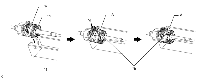
*1 Shift Lever Assembly - - *a Stopper *b Spring *c Nut *d Push in Note
-
If the stopper cannot be pushed in, slightly turn the nut clockwise and then push in the stopper again.
-
Make sure that the transmission control cable assembly is securely locked.
-
-
Connect the transmission control cable assembly to the shift lever assembly.
Note
-
The shift lever should be in N.
-
Connect the transmission control cable assembly all the way to the base of the pin.
-
-
-
INSTALL SHIFT LEVER KNOB SUB-ASSEMBLY
-
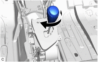
Turn the shift lever knob sub-assembly clockwise to install the shift lever knob sub-assembly.
-
-
INSTALL REAR CONSOLE BOX ASSEMBLY
-
INSPECT SHIFT LEVER POSITION
-
ADJUST SHIFT LEVER POSITION