TRANSMISSION CONTROL CABLE(for TMUK Made) INSTALLATION
PROCEDURE
-
INSTALL TRANSMISSION CONTROL CABLE ASSEMBLY
-
Pass the transmission control cable assembly into the vehicle and install the transmission control cable assembly to the vehicle body with the 2 nuts.
- Torque:
- 5.0 N*m { 51 kgf*cm, 44 in.*lbf }
-
Connect the transmission control cable assembly to the rear engine mounting insulator with the bolt.
- Torque:
- 5.0 N*m { 51 kgf*cm, 44 in.*lbf }
-
Connect the transmission control cable assembly to the No. 1 transmission control cable bracket with a new clip.
-
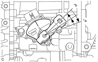
*a P Position *b N Position Turn the control shaft lever clockwise until it stops, then turn it counterclockwise 2 notches.
-
Connect the transmission control cable assembly to the control shaft lever with the nut.
- Torque:
- 12 N*m { 122 kgf*cm, 9 ft.*lbf }
-
Turn the nut of the transmission control cable assembly approximately 180° counterclockwise. While holding the nut in place, push in the stopper until it clicks twice.
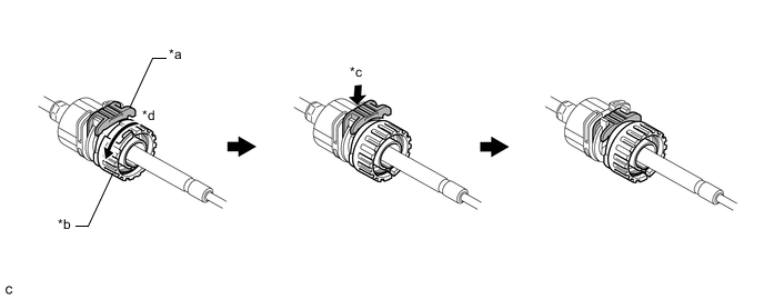
*a Stopper *b Nut *c Push in *d Turn approximately 180° Tech Tips
If the stopper cannot be pushed in, slightly turn the nut clockwise and then push in the stopper again.
-
Connect the transmission control cable assembly to the shift lever assembly. Check that the spring is positioned at (A) and push in the stopper.
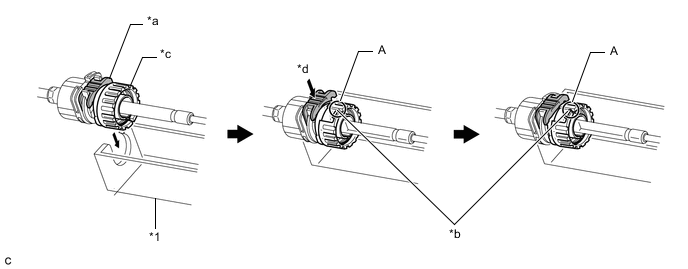
*1 Shift Lever Assembly - - *a Stopper *b Spring *c Nut *d Push in Note
-
If the stopper cannot be pushed in, slightly turn the nut clockwise and then push in the stopper again.
-
Make sure that the transmission control cable assembly is securely locked.
-
-
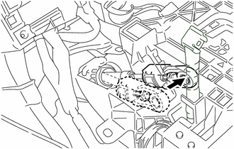
Connect the transmission control cable assembly to the shift lever assembly.
Note
-
The shift lever should be in N.
-
Connect the transmission control cable assembly all the way to the base of the pin.
-
-
-
ADJUST SHIFT LEVER POSITION
-
INSTALL FRONT NO. 1 FLOOR HEAT INSULATOR
-
Install the front No. 1 floor heat insulator to the vehicle body with the 3 nuts.
- Torque:
- 5.5 N*m { 56 kgf*cm, 49 in.*lbf }
-
-
INSTALL FRONT EXHAUST PIPE ASSEMBLY (TWC: Front and Rear Catalyst) (for 1ZR-FAE)
-
INSTALL FRONT EXHAUST PIPE ASSEMBLY (TWC: Rear Catalyst) (for 8NR-FTS)
-
INSTALL FRONT CENTER FLOOR BRACE SUB-ASSEMBLY (for 1ZR-FAE)
-
INSTALL FRONT CENTER FLOOR BRACE SUB-ASSEMBLY (for 8NR-FTS)
-
INSTALL BATTERY CARRIER ASSEMBLY (for 1ZR-FAE)
-
INSTALL BATTERY (for 1ZR-FAE)
-
INSTALL AIR CLEANER CASE SUB-ASSEMBLY (for 1ZR-FAE)
-
INSTALL AIR CLEANER CASE SUB-ASSEMBLY (for 8NR-FTS)
-
INSTALL AIR CLEANER CAP SUB-ASSEMBLY (for 1ZR-FAE)
-
INSTALL AIR CLEANER CAP WITH AIR CLEANER HOSE (for 8NR-FTS)
-
INSTALL NO. 2 CYLINDER HEAD COVER (for 1ZR-FAE)
-
CONNECT CABLE TO NEGATIVE BATTERY TERMINAL
Note
When disconnecting the cable, some systems need to be initialized after the cable is reconnected.
-
INSTALL REAR CONSOLE BOX ASSEMBLY
-
INSPECT SHIFT LEVER POSITION
-
INSPECT FOR EXHAUST GAS LEAK (for 1ZR-FAE)
-
INSPECT FOR EXHAUST GAS LEAK (for 8NR-FTS)