CONTINUOUSLY VARIABLE TRANSAXLE ASSEMBLY(for 1ZR-FAE) REMOVAL

CAUTION / NOTICE / HINT
CAUTION:
The engine assembly with continuously variable transaxle assembly is very heavy. Be sure to follow the procedure described in the repair manual, or the engine lifter may suddenly drop.
PROCEDURE
-
REMOVE FLYWHEEL HOUSING UNDER COVER
-
REMOVE DRIVE PLATE AND TORQUE CONVERTER ASSEMBLY SETTING BOLT
-
Turn the crankshaft to gain access to the 6 drive plate and torque converter assembly setting bolts and remove each drive plate and torque converter assembly setting bolt while holding the crankshaft pulley bolt with a wrench.
Tech Tips
There will be one black colored drive plate and torque converter assembly setting bolt.
-
-
REMOVE FRONT SUSPENSION MEMBER REAR BRACE LH
-
REMOVE FRONT SUSPENSION MEMBER REAR BRACE RH
Tech Tips
Perform the same procedure as for the LH side.
-
REMOVE FRONT SUSPENSION CROSSMEMBER SUB-ASSEMBLY
-
REMOVE ENGINE ASSEMBLY WITH TRANSAXLE
-
REMOVE FRONT ENGINE MOUNTING INSULATOR
-
REMOVE REAR ENGINE MOUNTING INSULATOR
-
REMOVE WIRE HARNESS CLAMP BRACKET
-
INSTALL ENGINE HANGER
-
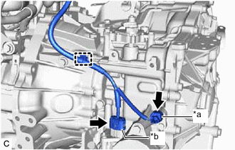
REMOVE NO. 5 WATER BY-PASS HOSE
-
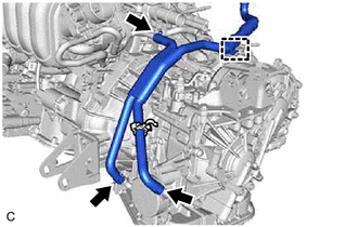
Disengage the clamp.
-
Slide the 3 clips and remove the No. 5 water by-pass hose from the transmission oil cooler and engine assembly.
-
-
DISCONNECT ENGINE WIRE
-
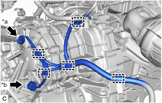
*a Transmission Revolution Sensor (NOUT) Connector *b Oil Pressure Sensor Connector Disconnect the transmission revolution sensor (NOUT) connector.
-
Disconnect the oil pressure sensor connector.
-
Disengage the 5 clamps.
-
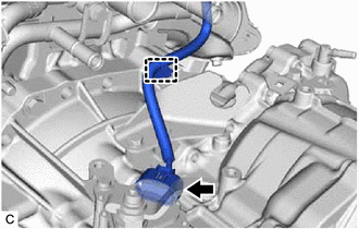
Disconnect the park/neutral position switch assembly connector.
-
Disengage the clamp.
-
*a Transmission Revolution Sensor (NIN) Connector *b Transmission Wire Connector Disconnect the transmission revolution sensor (NIN) connector.
-
Disconnect the transmission wire connector.
-
Disengage the clamp.
-
-
REMOVE FLYWHEEL HOUSING SIDE COVER
-
REMOVE STARTER ASSEMBLY
-
REMOVE CONTINUOUSLY VARIABLE TRANSAXLE ASSEMBLY
-
Using a transmission jack attachment, set the continuously variable transaxle assembly on a transmission jack.
Note
-
Secure the continuously variable transaxle assembly to the transmission jack using a suitable adapter, such as a rope or attachment.
-
To prevent the transaxle oil (CVT) pan sub-assembly from deforming, do not place any attachments under the transaxle oil (CVT) pan sub-assembly.
-
Hold the engine assembly with a suitable adapter, such as a rope, during the operation.
-
-
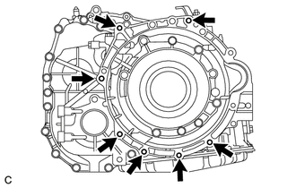
Remove the 7 bolts and continuously variable transaxle assembly from the engine assembly.
Note
To prevent damage to the 2 knock pins, do not pry between the continuously variable transaxle assembly and engine assembly.
-
-
REMOVE TORQUE CONVERTER ASSEMBLY
-
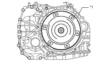
*1 Torque Converter Assembly Remove the torque converter assembly from the continuously variable transaxle assembly.
Note
Remove the torque converter assembly from the input shaft horizontally.
-
-
REMOVE CVT OIL PUMP TYPE T OIL SEAL
CAUTION:
-
Do not remove the front oil pump assembly from the continuously variable transaxle assembly main body, as there is a possibility of the entry of dust and foreign matter.
-
Clean the work area, the tools to be used, and other equipment, etc. thoroughly before the operation, as there is the possibility that a continuously variable transaxle assembly malfunction, which may prevent the vehicle from being driven, may occur if dust or fine foreign matter enters the continuously variable transaxle assembly.
-
Do not use cotton work gloves, cloths, paper towels, etc. that may produce lint, dust or foreign matter.
-
Perform the operation as quickly as possible, as dust and foreign matter may enter the continuously variable transaxle assembly while the torque converter assembly is not attached to it.
-
Do not use an air gun until the torque converter assembly has been installed, as it may cause dust and foreign matter to be stirred up.
-
Clean the tips of both the claws of SST and center bolt.
- SST
- 09308-10010
-
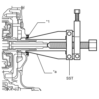
*1 CVT Oil Pump Type T Oil Seal *a Claw Using SST, remove the CVT oil pump type T oil seal from the continuously variable transaxle assembly.
Note
Pay attention to the angle of the claws of SST when opening them, and ensure that they do not come into contact with the oil pump housing, as there is the possibility that metal particles may be produced if they do.
-
-
REMOVE NO. 1 TRANSMISSION CONTROL CABLE BRACKET
-
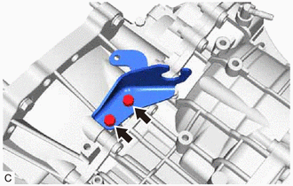
Remove the 2 bolts and No. 1 transmission control cable bracket from the continuously variable transaxle assembly.
-
-
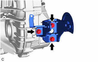
REMOVE FRONT ENGINE MOUNTING BRACKET
-
Remove the 4 bolts and front engine mounting bracket from the continuously variable transaxle assembly.
-
-
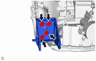
REMOVE REAR ENGINE MOUNTING BRACKET
-
Remove the 3 bolts and rear engine mounting bracket from the continuously variable transaxle assembly.
-
-
REMOVE ENGINE MOUNTING BRACKET LH
-
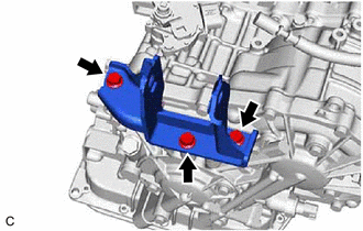
Remove the 3 bolts and engine mounting bracket LH from the continuously variable transaxle assembly.
-
-
REMOVE WIRE HARNESS CLAMP BRACKET
-
Remove the water by-pass hose clamp from the water by-pass hose clamp bracket.
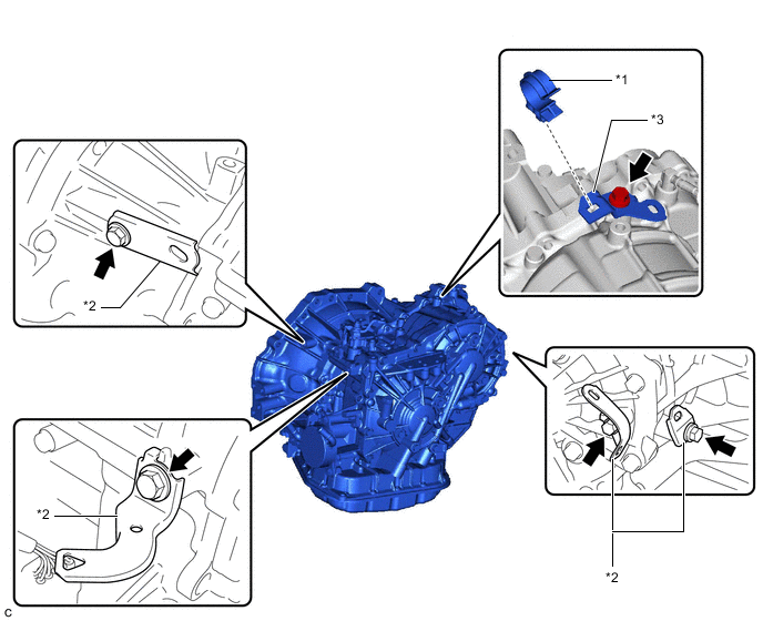
*1 Water By-pass Hose Clamp *2 Wire Harness Clamp Bracket *3 Water By-pass Hose Clamp Bracket - - -
Remove the 5 bolts, 4 wire harness clamp brackets and water by-pass hose clamp bracket from the continuously variable transaxle assembly.
-
-
REMOVE WITH HEAD STRAIGHT SCREW PLUG
Tech Tips
Perform this procedure only when replacement of the with head straight screw plug is necessary.
-
Remove the with head straight screw plug and gasket from the continuously variable transaxle assembly.
-
-
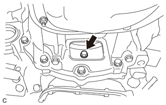
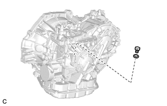
REMOVE NO. 1 BREATHER PLUG (CVT)
Tech Tips
Perform this procedure only when replacement of the No. 1 breather plug (CVT) is necessary.
-
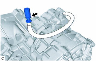
Remove the No. 1 breather plug (CVT) from the breather plug hose.
-
-
INSPECT TORQUE CONVERTER ASSEMBLY
-
INSPECT DRIVE PLATE AND RING GEAR SUB-ASSEMBLY