CONTINUOUSLY VARIABLE TRANSAXLE SYSTEM, Diagnostic DTC:P1585
| DTC Code | DTC Name |
|---|---|
| P1585 | Acceleration Sensor Circuit |
DESCRIPTION
The ECM determines the vehicle inclination based on a signal from the airbag sensor assembly (yaw rate and acceleration sensor). If a malfunction is determined in the airbag sensor assembly (yaw rate and acceleration sensor) based on a malfunction signal from the brake actuator assembly, the ECM cancels neutral control as a fail-safe function.
Tech Tips
-
The signal of the airbag sensor assembly (yaw rate and acceleration sensor) is sent to the brake actuator assembly via the CAN communication system.
-
If CAN communication DTCs are output, perform troubleshooting for those DTCs first.
| DTC No. | Detection Item | DTC Detection Condition | Trouble Area | MIL | Memory |
|---|---|---|---|---|---|
| P1585 | Acceleration Sensor Circuit |
|
|
Does not come on | DTC stored |
WIRING DIAGRAM
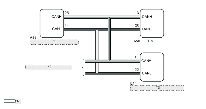
| *1 | Brake actuator assembly (Skid control ECU) |
| *2 | to CAN communication system |
| *3 | Airbag sensor assembly (Yaw rate and acceleration sensor) |
| *4 | CAN Communication Line |
PROCEDURE
-
CHECK DTC OUTPUT
-
Connect the GTS to the DLC3.
-
Turn the ignition switch to ON.
-
Turn the GTS on.
-
Check for DTCs.
Powertrain > Engine and ECT > Trouble CodesResult Result Proceed to DTC U0129 is not output A DTC U0129 is output B
B 
GO TO CAN COMMUNICATION SYSTEM Click here
A 
-
-
READ VALUE USING GTS (G SENSOR)
-
Connect the GTS to the DLC3.
-
Turn the ignition switch to ON.
-
Turn the GTS on.
-
Enter the following menus: Powertrain / Engine and ECT / Data List / Primary.
-
In accordance with the display on the GTS, read the Data List.
Powertrain > Engine and ECT > Data ListTester Display Measurement Item Range Normal Condition Diagnostic Note G Sensor Converted output voltage of yaw rate and acceleration sensor min.: 0 V
max.: 5 V
Displays converted voltage of yaw rate and acceleration sensor
-
2.31 V to 2.69 V: Vehicle on level ground
-
1.88 V to 2.5 V: Decelerating
-
2.5 V to 3.11 V: Accelerating
-
Set to 1.87 V: G sensor malfunction
-
Set to 1.87 V: Communication malfunction
- Result Result Proceed to Data display is not within Normal Condition range A Data display is within Normal Condition range B -
B
REPLACE BRAKE ACTUATOR BRACKET ASSEMBLY Click here
A
-
-
REPLACE AIR BAG SENSOR ASSEMBLY (YAW RATE AND ACCELERATION SENSOR)
-
Replace the airbag sensor assembly (yaw rate and acceleration sensor).
Result Proceed to NEXT
NEXT
-
-
PERFORM INITIALIZATION
Note
-
Performing Reset Memory will clear the learned value of the yaw rate and acceleration sensor (deceleration sensor zero point calibration) and the CVT oil pressure (CVT oil pressure calibration). Make sure to perform Reset Memory, yaw rate and acceleration sensor zero point calibration, and CVT oil pressure calibration when replacing any of the parts shown in the following table:
Replaced Part
-
Continuously variable transaxle assembly
-
ECM
-
Oil pressure sensor
-
Airbag sensor assembly (Yaw rate and acceleration sensor)
-
-
After performing Reset Memory, always perform yaw rate and acceleration sensor (deceleration sensor zero point) calibration first, and then CVT oil pressure calibration.
-
Always perform calibration with the vehicle on level ground.
-
Do not shake or vibrate the vehicle during calibration.
-
Using the GTS, perform Reset Memory, deceleration sensor zero point calibration and CVT oil pressure calibration.
-
Check for DTCs again.
Result Proceed to NEXT
NEXT
END
-