CONTINUOUSLY VARIABLE TRANSAXLE SYSTEM, Diagnostic DTC:P0962, P0963, P0966, P0967
| DTC Code | DTC Name |
|---|---|
| P0962 | Pressure Control Solenoid "A" Control Circuit Low (Shift Solenoid Valve DS1) |
| P0963 | Pressure Control Solenoid "A" Control Circuit High (Shift Solenoid Valve DS1) |
| P0966 | Pressure Control Solenoid "B" Control Circuit Low (Shift Solenoid Valve DS2) |
| P0967 | Pressure Control Solenoid "B" Control Circuit High (Shift Solenoid Valve DS2) |
DESCRIPTION
Using the shift solenoid valve DS1 (inflow to the primary pulley) and shift solenoid valve DS2 (outflow from the primary pulley), the ECM controls the line pressure and fluid volume input to and output from the primary pulley according to the vehicle speed and accelerator pedal angle. As a fail-safe function, if a is short or open is detected in a solenoid circuit, the ECM stops current to the faulty solenoid.
| DTC No. | Detection Item | DTC Detection Condition | Trouble Area | MIL | Memory |
|---|---|---|---|---|---|
| P0962 | Pressure Control Solenoid "A" Control Circuit Low (Shift Solenoid Valve DS1) |
|
|
Comes on | DTC stored |
| P0963 | Pressure Control Solenoid "A" Control Circuit High (Shift Solenoid Valve DS1) |
|
|
Comes on | DTC stored |
| P0966 | Pressure Control Solenoid "B" Control Circuit Low (Shift Solenoid Valve DS2) |
|
|
Comes on | DTC stored |
| P0967 | Pressure Control Solenoid "B" Control Circuit High (Shift Solenoid Valve DS2) |
|
|
Comes on | DTC stored |
MONITOR DESCRIPTION
These DTCs indicate an open or short circuit in the shift solenoid valve DS1 or DS2 circuit. When there is an open or short circuit in the shift solenoid valve DS1 or DS2 circuit, the ECM detects the problem, illuminates the MIL and stores a DTC.
WIRING DIAGRAM
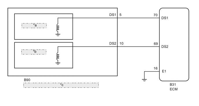
| *a | Shift Solenoid Valve DS1 |
| *b | Shift Solenoid Valve DS2 |
| *c | Continuously Variable Transaxle Assembly (Transmission Wire) |
PROCEDURE
-
PERFORM ACTIVE TEST USING GTS (CONTROL THE SHIFT POSITION)
-
Connect the GTS to the DLC3.
-
Turn the ignition switch to ON.
-
Turn the GTS on.
-
Enter the following menus: Powertrain / Engine and ECT / Data List.
Powertrain > Engine and ECT > Data ListTester Display Measurement Item Range Normal Condition Diagnostic Note Shift Status ECM gearshift command 1st, 2nd, 3rd, 4th or 5th Same as actual shift position *1 Tech Tips
*1:"Shift Status" is a signal divided into 5 gear positions for Active Test.
It does not express gear ratios for normal driving and gear positions for 7-speed sport sequential shiftmatic mode.
-
Enter the following menus: Powertrain / Engine and ECT / Active Test.
-
In accordance with the display on the GTS, perform the Active Test.
Powertrain > Engine and ECT > Active TestTester Display Measurement Item Control Range Diagnostic Note Control the Shift Position Operates the shift solenoid valves to allow the gear position to be manually selected [1st - 2nd - 3rd - 4th - 5th]
Reference gear ratios:
1st (2.4 gear ratio max.) - 2nd (1.5) - 3rd (1.0) - 4th (0.7) - 5th (0.43 gear ratio min.)
-
Press "→" button: Shift up
-
Press "←" button: Shift down
Used to check the operation of the shift solenoid valves.
[Vehicle Condition]
Perform at a vehicle speed of 45 km/h (28 mph) or less.
Note
Performing this test at speeds other than those specified in "Vehicle Condition" will damage the transaxle.
Tech Tips
Perform "Control the Shift Position" while monitoring "Shift Status" to confirm actual gear position.
Result Result Proceed to Gear position does not change A Gear position changes B -
B 
REPLACE ECM Click here
A 
-
-
INSPECT TRANSMISSION WIRE (SHIFT SOLENOID VALVE DS1 AND DS2)
-
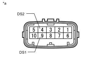
*a Component without harness connected
(Transmission Wire)
Disconnect the B90 transmission wire connector.
-
Measure the resistance according to the value(s) in the table below.
Standard Resistance Tester Connection Condition Specified Condition 4 (DS2) -Body ground and other terminals 20°C (68°F) 11 to 13 Ω 9 (DS1) - Body ground and other terminals 20°C (68°F) 11 to 13 Ω -
Connect the B90 transmission wire connector.
Result Proceed to OK NG
NG
REPLACE CONTINUOUSLY VARIABLE TRANSAXLE ASSEMBLY Click here
OK
-
-
CHECK HARNESS AND CONNECTOR (TRANSMISSION WIRE - ECM)
-
Disconnect the B31 ECM connector.
-
Measure the resistance according to the value(s) in the table below.
Standard Resistance Tester Connection Condition Specified Condition B31-70 (DS1) - B31-16 (E1) 20°C (68°F) 11 to 13 Ω B31-69 (DS2) - B31-16 (E1) 20°C (68°F) 11 to 13 Ω -
Connect the B31 ECM connector.
Result Proceed to OK NG
NG 
REPAIR OR REPLACE HARNESS OR CONNECTOR (TRANSMISSION WIRE - ECM)
OK
-
-
REPLACE ECM
-
Replace the ECM.
for 1ZR-FE: Click here
for 2ZR-FE: Click here
Result Proceed to NEXT
NEXT
PERFORM INITIALIZATION Click here
-
-
REPLACE CONTINUOUSLY VARIABLE TRANSAXLE ASSEMBLY
-
Replace the continuously variable transaxle assembly.
Result Proceed to NEXT
NEXT
PERFORM INITIALIZATION Click here
-
-
REPLACE ECM
-
Replace the ECM.
for 1ZR-FE: Click here
for 2ZR-FE: Click here
Result Proceed to NEXT
NEXT
PERFORM INITIALIZATION Click here
-