SHIFT AND SELECT ACTUATOR INSTALLATION
PROCEDURE
-
INSTALL SHIFT AND SELECT ACTUATOR ASSEMBLY
-
Install the breather plug cap to the shift and select actuator assembly.
-
Install the breather protector to the shift and select actuator assembly with the bolt.
- Torque:
- 18 N*m { 184 kgf*cm, 13 ft.*lbf }
-
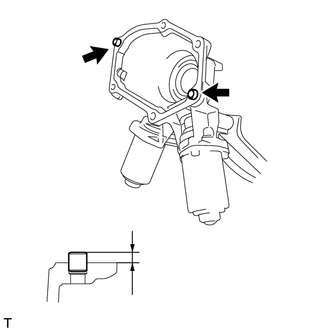
Using a plastic hammer, tap in 2 new ring pins to the specified protrusion height.
Protrusion Height 5.2 to 5.8 mm (0.205 to 0.228 in.) -
Clean and degrease the contact surfaces between the shift and select actuator and front transaxle case.
-
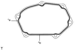
*a FIPG *b Seal Diameter 1.2 mm (0.0472 in.) Apply FIPG to the shift and select actuator as shown illustration.
FIPG Toyota Genuine Seal Packing 1281, Three Bond 1281 or equivalent. Note
-
Remove any oil from the contact surfaces.
-
Install the parts within 10 minutes of application. Otherwise, the packing (FIPG) material must be removed and reapplied.
-
-
When replacing the shift and select actuator with a new one:
-
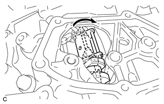
Move the inner select lever as shown in the illustration.
-
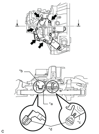
*a Shift and Select Lever Shaft Head *b Shift Actuator Plate *c Select Actuator Plate *d Inner Select Lever Install the shift and select actuator and wire harness clamp bracket to the front transaxle case with the 6 bolts.
- Torque:
- 18 N*m { 184 kgf*cm, 13 ft.*lbf }
Note
-
Securely engage the shift actuator plate to the shift and select lever shaft head.
-
Securely engage the select actuator plate to the inner select lever.
-
-
When reusing the shift and select actuator:
-
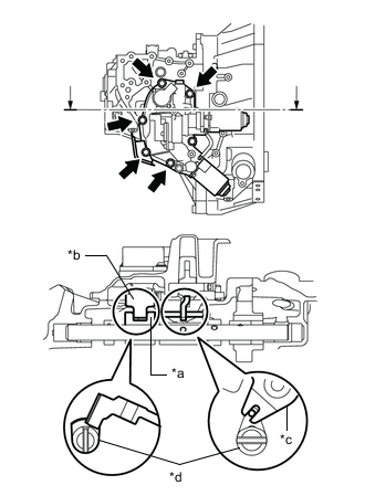
*a Shift and Select Lever Shaft Head *b Shift Actuator Plate *c Select Actuator Plate *d Inner Select Lever Install the shift and select actuator to the front transaxle case with the 6 bolts.
- Torque:
- 18 N*m { 184 kgf*cm, 13 ft.*lbf }
Note
-
Securely engage the shift actuator plate to the shift and select lever shaft head.
-
Securely engage the select actuator plate to the inner select lever.
-
-
Install the wire harness clamp bracket to the shift and select actuator with the bolt.
- Torque:
- 12.5 N*m { 127 kgf*cm, 9 ft.*lbf }
-
Install the wire harness clamp bracket to the shift and select actuator with the bolt.
- Torque:
- 8.0 N*m { 82 kgf*cm, 71 in.*lbf }
-
-
CONNECT WIRE HARNESS
-
Connect the connector and 3 wire harness clamps.
-
Connect the 6 connectors.
-
Connect the 5 wire harness clamps.
-
-
INSTALL NO. 1 AIR TUBE
-
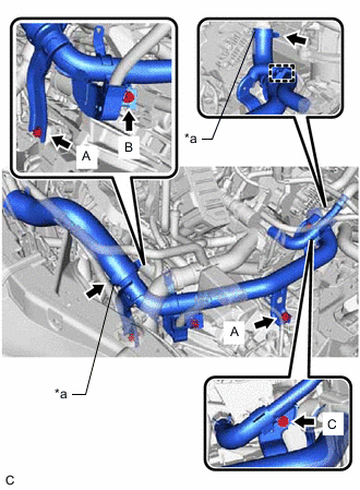
*a Hose Clamp Install the No. 1 air tube and tighten the 2 hose clamps.
- Torque:
- 6.5 N*m { 66 kgf*cm, 58 in.*lbf }
Note
One minute after tightening the hose clamps, check that residual torque is 3.2 N*m (33 kgf*cm, 28 in.*lbf) or more.
-
Install the 4 bolts.
- Torque:
- Bolt A
- 20 N*m { 204 kgf*cm, 15 ft.*lbf }
- Bolt B
- 12.5 N*m { 127 kgf*cm, 9 ft.*lbf }
- Bolt C
- 9.8 N*m { 100 kgf*cm, 87 in.*lbf }
-
Connect the wire harness clamp.
-
-
INSTALL AIR CLEANER BRACKET
-
INSTALL FUEL FILTER SUPPORT
-
CONNECT ENGINE WIRE
-
INSTALL FUEL FILTER ASSEMBLY
-
INSTALL BATTERY
-
CONNECT CABLE TO NEGATIVE BATTERY TERMINAL
Note
When disconnecting the cable, some systems need to be initialized after the cable is reconnected.
-
PERFORM INITIALIZATION OF MULTI-MODE MANUAL TRANSAXLE SYSTEM
-
PERFORM LEARNING OF MULTI-MODE MANUAL TRANSAXLE SYSTEM
-
PERFORM SYNCHRONIZATION POSITION CALIBRATION