MULTI-MODE MANUAL TRANSAXLE SYSTEM, Diagnostic DTC:P0617
| DTC Code | DTC Name |
|---|---|
| P0617 | Starter Relay Circuit High |
DESCRIPTION
If engine speed and battery voltage are above a certain level while the vehicle is being driven (not start condition) and the STA signal is on for a certain amount of time, this DTC is stored.
| DTC No. | Detection Item | DTC Detection Condition | Trouble Area | MIL | Warning Indicate | Memory |
|---|---|---|---|---|---|---|
| P0617 | Starter Relay Circuit High | Following conditions (1), (2) and (3) met for 20 seconds (1-trip detection logic):
|
|
Comes on | Comes on | DTC stored |
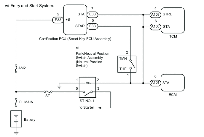
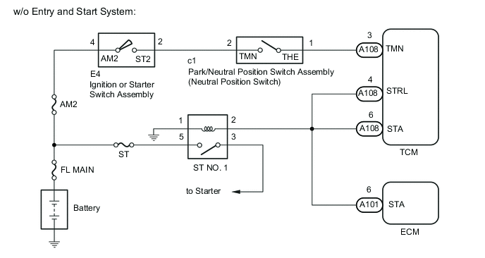
WIRING DIAGRAM
CAUTION / NOTICE / HINT
Tech Tips
If DTC P0703 is output, troubleshoot this code first.
PROCEDURE
-
READ VALUE USING GTS (STA SWITCH SIGNAL)
-
Connect the GTS to the DLC3.
-
Turn the ignition switch to ON.
-
Turn the GTS on.
-
Enter the following menus: Powertrain / Multi-Mode M/T / Data List / STA Switch Signal.
-
According to the display on the GTS, read the Data List.
Powertrain > Multi-Mode M/T > Data ListTester Display Measurement Item Range Normal Condition Diagnostic Note STA Switch Signal STA signal OFF or ON OFF: Not cranking
ON: Cranking
-
Powertrain > Multi-Mode M/T > Data ListTester Display STA Switch Signal OK OFF is displayed in the Data List when not cranking. Result Result Proceed to NG (w/ Entry and Start System) A NG (w/o Entry and Start System) B OK C
B 
INSPECT ST NO. 1 RELAY Click here
C 
CHECK FOR INTERMITTENT PROBLEMS Click here
A 
-
-
INSPECT NEUTRAL POSITION SWITCH
-
Inspect the neutral position switch assembly.
Result Proceed to OK NG
NG
REPLACE NEUTRAL POSITION SWITCH Click here
OK
-
-
REPAIR OR REPLACE HARNESS OR CONNECTOR (STA SIGNAL CIRCUIT)
-
Repair or replace the harness or connector (neutral position switch - certification ECU - ST No. 1 relay - ECM - TCM).
Result Proceed to NEXT
NEXT
-
-
CHECK WHETHER DTC OUTPUT RECURS
-
Connect the GTS to the DLC3.
-
Turn the ignition switch to ON.
-
Turn the GTS on.
-
Clear the DTCs.
Powertrain > Multi-Mode M/T > Clear DTCs -
Drive the vehicle at more than 20 km/h (12.4 mph) for more than 20 seconds.
-
Enter the following menus: Powertrain / Multi-Mode M/T.
Powertrain > Multi-Mode M/T > Trouble Codes -
Read the DTCs.
Result Result Proceed to DTC P0617 is output A DTCs are not output B
B
END
A
-
-
REPLACE TCM
-
Replace the TCM.
Result Proceed to NEXT
NEXT
-
-
PERFORM INITIALIZATION
-
Perform the initialization and learning procedure.
Result Proceed to NEXT
NEXT
END
-
-
INSPECT ST NO. 1 RELAY
-
Remove the ST NO. 1 relay from the engine room relay block and junction block assembly.
-
Enter the following menus: Powertrain / Multi-Mode M/T / Data List / STA Switch Signal.
-
In accordance with the display on the GTS, read the Data List.
Powertrain > Multi-Mode M/T > Data ListTester Display Measurement Item Range Normal Condition Diagnostic Note STA Switch Signal STA signal OFF or ON OFF: Not cranking
ON: Cranking
-
Powertrain > Multi-Mode M/T > Data ListTester Display STA Switch Signal Result Result Proceed to ON is displayed in the Data List when not cranking. A OFF is displayed in the Data List when not cranking. B
B
REPLACE ST NO. 1 RELAY
A
-
-
INSPECT ECM
-
Disconnect the ECM connectors.
-
Enter the following menus: Powertrain / Multi-Mode M/T / Data List / STA Switch Signal.
-
In accordance with the display on the GTS, read the Data List.
Powertrain > Multi-Mode M/T > Data ListTester Display Measurement Item Range Normal Condition Diagnostic Note STA Switch Signal STA signal OFF or ON OFF: Not cranking
ON: Cranking
-
Powertrain > Multi-Mode M/T > Data ListTester Display STA Switch Signal Result Result Proceed to ON is displayed in the Data List when not cranking. A OFF is displayed in the Data List when not cranking. B
B
REPLACE ECM w/o Glow Plug Controller: Click here
REPLACE ECM w/ Glow Plug Controller: Click hereA
-
-
CHECK HARNESS AND CONNECTOR (TCM - ST RELAY - ECM)
-
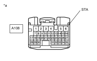
*a Front view of wire harness connector
(to TCM)
Disconnect the TCM connector.
-
Measure the voltage according to the value(s) in the table below.
Standard Voltage Tester Connection Condition Specified Condition A108-6 (STA) - Body ground Ignition switch off Below 1 V Result Proceed to OK NG
NG
REPAIR OR REPLACE HARNESS OR CONNECTOR
OK
-
-
REPLACE TCM
-
Replace the TCM.
Result Proceed to NEXT
NEXT
-
-
PERFORM INITIALIZATION
-
Perform the initialization and learning procedure.
Result Proceed to NEXT
NEXT
END
-