MULTI-MODE MANUAL TRANSAXLE SYSTEM, Diagnostic DTC:P0820
| DTC Code | DTC Name |
|---|---|
| P0820 | Gear Lever "X-Y" Position Sensor Circuit |
DESCRIPTION
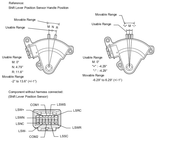
The TCM detects the shift lever position using the shift lever position sensor. The shift lever position sensor has two functions; detection and monitoring.
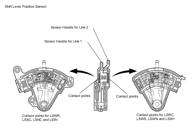
The shift lever position sensor consists of the Link 1 circuit that detects the shift lever positions, R, N, E and M, and the Link 2 circuit that detects the "+" and "-" positions. The circuits are connected to the shift lever via the respective links. The contact switches (6-contact switch for Link 1, and 2-contact switch for Link 2) of the circuits turn on and off in accordance with the fore-aft movement of the shift lever. The TCM detects the current shift lever position in accordance with the ON/OFF status of these contact switches. The transmission shift main switch detects the side-to-side movement of the shift lever. It turns off when the shift lever is in R, N, or E , and turns on when in M, "+", or "-" .
The shift lever position sensor and the transmission shift main switch convert the shift lever position into electric signals and output them to the TCM. The TCM detects the current shift lever position from these signals and operates the actuators to change the gear position.
| Contact Point | Shift Lever Position | ||||||
| R | N | E | M | - | + | ||
| Link 1 | LSRC | OFF | ON | ON | ON | ON | ON |
| LSWR | ON | OFF | OFF | OFF | OFF | OFF | |
| LSSC | ON | ON | OFF | OFF | OFF | OFF | |
| LSWS | OFF | OFF | ON | ON | ON | ON | |
| LSNC | ON | OFF | ON | ON | ON | ON | |
| LSWN | OFF | ON | OFF | OFF | OFF | OFF | |
| Link 2 | LSW- | OFF | OFF | OFF | OFF | ON | OFF |
| LSW+ | OFF | OFF | OFF | OFF | OFF | ON | |
| Transmission Shift Main Switch | OFF | OFF | OFF | ON | ON | ON | |
Tech Tips
The monitor runs when the shift lever is moved through each position (N, R, E, M, - and +).
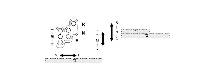
| *1 | Fore-aft Movement |
| *2 | (Shift Lever Position Sensor) |
| *3 | Side-to-side Movement (Transmission Shift Main Switch) |
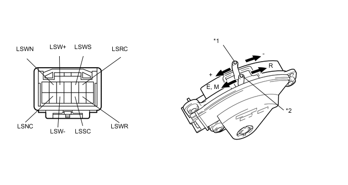
| *1 | Link 2 |
| *2 | Link 1 |
| DTC No. | Detection Item | DTC Detection Condition | Trouble Area | MIL | Warning Indicate | Memory |
|---|---|---|---|---|---|---|
| P0820 | Gear Lever "X-Y" Position Sensor Circuit | The TCM detects one of the following conditions: (1-trip detection logic)
The TCM detects one of the following conditions: (1-trip detection logic)
The TCM detects one of the following conditions: (1-trip detection logic)
The TCM detects the following conditions simultaneously: (1-trip detection logic)
|
|
Does not come on | Comes on | DTC stored |
WIRING DIAGRAM
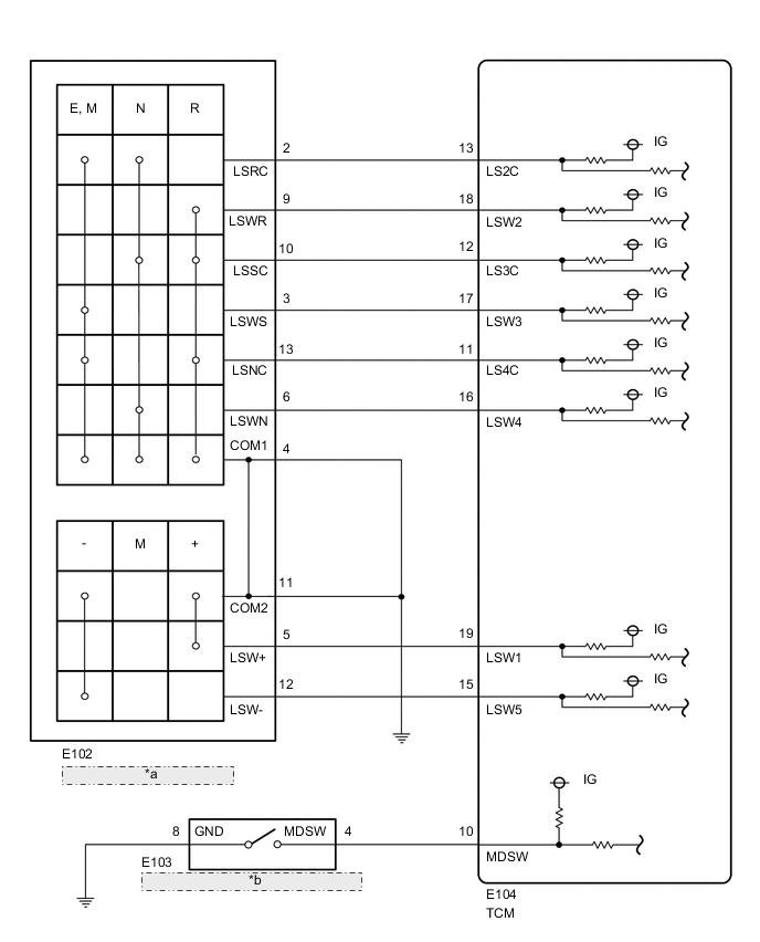
| *a | Shift Lever Position Sensor |
| *b | Shift Lock Control Unit Assembly (Transmission Shift Main Switch) |
PROCEDURE
-
READ VALUE USING GTS (SHIFT LEVER SWITCH AND SHIFT LEVER CHECK SIGNAL)
-
Connect the GTS to the DLC3.
-
Turn the ignition switch to ON.
-
Turn the GTS on.
-
Enter the following menus: Powertrain / Multi-Mode M/T / Data List / Shift Lever Switch Signal 1 - 5, and Shift Lever Check Signal 1 - 3.
-
Check that the normal condition specified in the following table is shown on the display when moving the shift lever to each position R, N, E, M, "+" , and "-".
Powertrain > Multi-Mode M/T > Data ListTester Display Measurement Item Range Normal Condition Diagnostic Note Shift Lever Switch Signal1 Shift lever switch signal "+" OFF or ON OFF: Shift lever not in "+"
ON: Shift lever in "+"
LSW1 (LSW+) terminal signal of TCM Shift Lever Switch Signal2 Shift lever switch signal R OFF or ON OFF: Shift lever not in R
ON: Shift lever in R
LSW2 (LSWR) terminal signal of TCM Shift Lever Switch Signal3 Shift lever switch signal M or E OFF or ON OFF: Shift lever in R or N
ON: Shift lever in E, M, "+" or "-"
LSW3 (LSWS) terminal signal of TCM Shift Lever Switch Signal4 Shift lever switch signal N OFF or ON OFF: Shift lever not in N
ON: Shift lever in N
LSW4 (LSWN) terminal signal of TCM Shift Lever Switch Signal5 Shift lever switch signal "-" OFF or ON OFF: Shift lever not in "-"
ON: Shift lever in "-"
LSW5 (LSW-) terminal signal of TCM Shift Lever Check Signal1 Check signal of shift lever switch signal 2 OFF or ON OFF: Shift lever in R
ON: Shift lever not in R
LS2C (LSRC) terminal signal of TCM
Reversal signal of LSW2 (LSWR) (ON and OFF reversed)
Shift Lever Check Signal2 Check signal of shift lever switch signal 3 OFF or ON OFF: Shift lever in E, M, "+" or "-"
ON: Shift lever in R or N
LS3C (LSSC) terminal signal of TCM
Reversal signal of LSW3 (LSWS) (ON and OFF reversed)
Shift Lever Check Signal3 Check signal of shift lever switch signal 4 OFF or ON OFF: Shift lever in N
ON: Shift lever not in N
LS4C (LSNC) terminal signal of TCM
Reversal signal of LSW4 (LSWN) (ON and OFF reversed)
Powertrain > Multi-Mode M/T > Data ListTester Display Shift Lever Switch Signal1 Shift Lever Switch Signal2 Shift Lever Switch Signal3 Shift Lever Switch Signal4 Shift Lever Switch Signal5 Shift Lever Check Signal1 Shift Lever Check Signal2 Shift Lever Check Signal3 OK When the shift lever is operated, the normal condition listed above is shown on the GTS. Result Proceed to OK NG
OK 
SYMPTOM SIMULATION AND DTC CHECK Click here
NG 
-
-
INSPECT SHIFT LOCK CONTROL UNIT ASSEMBLY (SHIFT LEVER POSITION SENSOR)
-
Disconnect the shift lever position sensor connector.
-
Measure the resistance according to the value(s) in the table below.
Tech Tips
The shift lever position sensor connector has no terminals in locations of 1, 8, 7, and 14.
Standard Resistance Tester Connection Condition Specified Condition 2 (LSRC) - 3 (LSWS) Shift lever in E, M, "+" or "-" Below 1 Ω 2 (LSRC) - 13 (LSNC) Below 1 Ω 3 (LSWS) - 4 (COM1) Below 1 Ω 3 (LSWS) - 11 (COM2) Below 1 Ω 2 (LSRC) - 4 (COM1) Shift lever in N, E, M, "+" or "-" Below 1 Ω 2 (LSRC) - 11 (COM2) Below 1 Ω 2 (LSRC) - 6 (LSWN) Shift lever in N Below 1 Ω 2 (LSRC) - 10 (LSSC) Below 1 Ω 4 (COM1)- 6 (LSWN) Below 1 Ω 6 (LSWN) - 10 (LSSC) Below 1 Ω 6 (LSWN) - 11 (COM2) Below 1 Ω 4 (COM1) - 5 (LSW+) Shift lever in "+" Below 1 Ω 5 (LSW+) - 11 (COM2) Below 1 Ω 4 (COM1) - 9 (LSWR) Shift lever in R Below 1 Ω 9 (LSWR) - 10 (LSSC) Below 1 Ω 9 (LSWR) - 11 (COM2) Below 1 Ω 9 (LSWR) - 13 (LSNC) Below 1 Ω 10 (LSSC) - 13 (LSNC) Below 1 Ω 4 (COM1) - 10 (LSSC) Shift lever in R or N Below 1 Ω 10 (LSSC) - 11 (COM2) Below 1 Ω 4 (COM1) - 11 (COM2) Always Below 1 Ω 4 (COM1) - 12 (LSW-) Shift lever in "-" Below 1 Ω 11 (COM2) - 12 (LSW-) Below 1 Ω 4 (COM1) - 13 (LSNC) Shift lever in R, E, M, "+" or "-" Below 1 Ω 11 (COM2) - 13 (LSNC) Below 1 Ω Result Proceed to OK NG
NG
REPLACE SHIFT LOCK CONTROL UNIT ASSEMBLY Click here
OK
-
-
CHECK HARNESS AND CONNECTOR (TCM - SHIFT LEVER POSITION SENSOR)
-
Disconnect the TCM connector.
-
Measure the resistance according to the value(s) in the table below.
Standard Resistance Tester Connection Condition Specified Condition E104-11 (LS4C) - E102-13 (LSNC) Always Below 1 Ω E104-12 (LS3C) - E102-10 (LSSC) Always Below 1 Ω E104-13 (LS2C) - E102-2 (LSRC) Always Below 1 Ω E104-15 (LSW5) - E102-12 (LSW-) Always Below 1 Ω E104-16 (LSW4) - E102-6 (LSWN) Always Below 1 Ω E104-17 (LSW3) - E102-3 (LSWS) Always Below 1 Ω E104-18 (LSW2) - E102-9 (LSWR) Always Below 1 Ω E104-19 (LSW1) - E102-5 (LSW+) Always Below 1 Ω E104-11 (LS4C) - Body ground Always 10 kΩ or higher E104-12 (LS3C) - Body ground Always 10 kΩ or higher E104-13 (LS2C) - Body ground Always 10 kΩ or higher E104-15 (LSW5) - Body ground Always 10 kΩ or higher E104-16 (LSW4) - Body ground Always 10 kΩ or higher E104-17 (LSW3) - Body ground Always 10 kΩ or higher E104-18 (LSW2) - Body ground Always 10 kΩ or higher E104-19 (LSW1) - Body ground Always 10 kΩ or higher Result Proceed to OK NG
NG
REPAIR OR REPLACE HARNESS OR CONNECTOR
OK
-
-
CHECK HARNESS AND CONNECTOR (SHIFT LEVER POSITION SENSOR - BODY GROUND)
-
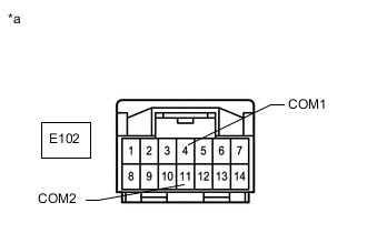
*a Front view of wire harness connector
(to Shift Lever Position Switch)
Measure the resistance according to the value(s) in the table below.
Standard Resistance Tester Connection Condition Specified Condition E102-4 (COM1) - Body ground Always Below 1 Ω E102-11 (COM2) - Body ground Always Below 1 Ω Result Proceed to OK NG
NG
REPAIR OR REPLACE HARNESS OR CONNECTOR
OK
-
-
REPLACE TCM
-
Replace the TCM.
for LHD: Click here
for RHD: Click here
Result Proceed to NEXT
NEXT
-
-
PERFORM INITIALIZATION
-
Perform the initialization and learning procedure.
Result Proceed to NEXT
NEXT
END
-