MULTI-MODE MANUAL TRANSAXLE SYSTEM, Diagnostic DTC:P0920
| DTC Code | DTC Name |
|---|---|
| P0920 | Gear Shift Forward Actuator Circuit |
DESCRIPTION
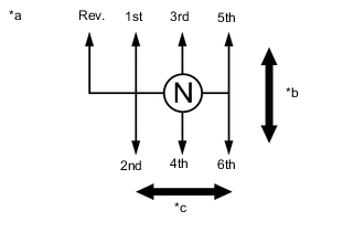
| *a | Shift and Select Actuator Operation |
| *b | Shift Direction |
| *c | Select Direction |
The shift and select actuator is operated by the TCM and changes the transaxle gear by the shift and select lever shaft movement. An electric motor (shift motor) moves the shift and select lever shaft in the shift direction, and the shift stroke sensor, which is mounted on the shift and select actuator assembly, detects the shift position. The TCM monitors the electrical current and shift motor output terminal voltage, and detects malfunctions in the shift motor circuit.
| DTC No. | Detection Item | DTC Detection Condition | Trouble Area | MIL | Warning Indicate | Memory |
|---|---|---|---|---|---|---|
| P0920 | Gear Shift Forward Actuator Circuit | The TCM detects the following conditions: (1-trip detection logic)
The TCM detects the following conditions: (1-trip detection logic)
The TCM detects the following conditions: (1-trip detection logic)
|
|
Does not come on | Comes on | DTC stored |
-
*1: A short between the shift motor circuit and the body ground is suspected.
-
*2: A short between the shift motor circuit and the +B circuit is suspected.
-
*3: An open in the shift motor circuit is suspected. When the motor current does not flow to the ECU terminals despite the ECU ordering the shift motor to operate, the ECU stores this DTC.
-
*4: An open in the shift motor circuit is suspected. When the difference is more than the threshold despite the ECU not ordering the shift motor to operate, the ECU stores this DTC.
WIRING DIAGRAM
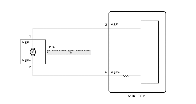
| *a | Shift and Select Actuator Assembly (Shift Motor) |
CAUTION / NOTICE / HINT
Note
When installing parts related to the multi-mode manual transaxle system, perform the initialization and learning and synchronization position calibration procedures. In addition, the required operations differ according to the parts to be installed. Proceed with the operation in the order shown in the table below.
| Part Installed | Part Installed | See Procedure |
|---|---|---|
|
1. Initialization of multi-mode manual transaxle system [Tester display: Initialization of ECU] |
|
| 2. Learning of multi-mode manual transaxle system | ||
| 3. Synchronization position calibration | ||
|
1. Initialization of multi-mode manual transaxle system [Tester display: Initialization of transmission] |
|
| 2. Learning of multi-mode manual transaxle system | ||
| 3. Synchronization position calibration | ||
|
1. Initialization of multi-mode manual transaxle system [Tester display: Initialization of clutch] |
|
| 2. Learning of multi-mode manual transaxle system |
If the sensor or actuator is installed without the initialization and learning procedures, it may cause driving performance degradation or system component breakage.
PROCEDURE
-
INSPECT TCM (MSF TERMINAL VOLTAGE)
Result Proceed to OK NG
-
Turn the ignition switch to ON.
-
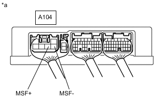
*a Component with harness connected
(TCM)
Measure the voltage according to the value(s) in the table below.
Standard Voltage Tester Connection Condition Specified Condition A104-4 (MSF+) - Body ground Ignition switch ON 4.0 to 7.0 V A104-3 (MSF-) - Body ground Ignition switch ON 4.0 to 7.0 V -
Turn the ignition switch off.
Result Proceed to OK NG
OK 
CHECK INTERMITTENT PROBLEMS Click here
NG 
-
-
CHECK TERMINAL CONDITION (TCM)
Result Proceed to OK NG
-
Disconnect the TCM connector.
-
Check the connections of the TCM connector.
OK The TCM and wire harness connectors and connector terminals are connected securely and are not bent, rusted, or damaged. Result Proceed to OK NG
NG
CONNECT CORRECTLY
OK
-
-
CHECK SHIFT MOTOR CIRCUIT
Result Proceed to OK NG
-
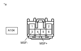
*a Front view of wire harness connector
(to TCM)
Measure the resistance according to the value(s) in the table below.
Standard Resistance Tester Connection Condition Specified Condition A104-4 (MSF+) - A104-3 (MSF-) Always Below 10 Ω A104-4 (MSF+) - Body ground Always 10 kΩ or higher A104-3 (MSF-) - Body ground Always 10 kΩ or higher Result Proceed to OK NG
NG 
CHECK TERMINAL CONDITION (SHIFT MOTOR) Click here
OK
-
-
REPLACE TCM
-
Replace the TCM.
for LHD: Click here
for RHD: Click here
Result Proceed to NEXT
NEXT
-
-
PERFORM INITIALIZATION
-
Perform the initialization and learning procedure.
Result Proceed to NEXT
NEXT
END
-
-
CHECK TERMINAL CONDITION (SHIFT MOTOR)
Result Proceed to OK NG
-
Disconnect the shift motor connector.
-
Check the connections of the shift motor connector.
OK The shift motor and wire harness connectors and connector terminals are connected securely and are not bent, rusted, or damaged. Result Proceed to OK NG
NG
CONNECT CORRECTLY
OK
-
-
CHECK HARNESS AND CONNECTOR (TCM - SHIFT MOTOR)
Result Proceed to OK NG
-
Measure the resistance according to the value(s) in the table below.
Standard Resistance Tester Connection Switch Condition Specified Condition A104-4 (MSF+) - B139-2 (MSF+) Always Below 1 Ω A104-3 (MSF-) - B139-1 (MSF-) Always Below 1 Ω A104-4 (MSF+) or B139-2 (MSF+) - Body ground Always 10 kΩ or higher A104-3 (MSF-) or B139-1 (MSF-) - Body ground Always 10 kΩ or higher Result Proceed to OK NG
NG
REPAIR OR REPLACE HARNESS OR CONNECTOR
OK
-
-
INSPECT SHIFT AND SELECT ACTUATOR ASSEMBLY (SHIFT MOTOR)
Result Proceed to OK NG
-
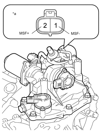
*a Component without harness connected
(Shift and Select Actuator Assembly (Shift Motor))
Measure the resistance according to the value(s) in the table below.
Standard Resistance Tester Connection Condition Specified Condition 1 (MSF-) - 2 (MSF+) Always Below 10 Ω 1 (MSF-) - Body ground Always 10 kΩ or higher 2 (MSF+) - Body ground Always 10 kΩ or higher Result Proceed to OK NG
OK
CHECK INTERMITTENT PROBLEMS Click here
NG
-
-
REPLACE SHIFT AND SELECT ACTUATOR ASSEMBLY
-
Replace the shift and select actuator assembly.
Result Proceed to NEXT
NEXT
-
-
PERFORM INITIALIZATION
-
Perform the initialization and learning procedure.
Result Proceed to NEXT
NEXT
END
-