TRANSMISSION CONTROL CABLE INSTALLATION
PROCEDURE
-
INSTALL TRANSMISSION CONTROL CABLE ASSEMBLY
-
Pass the transmission control cable assembly into the vehicle and install the transmission control cable assembly to the vehicle body with the 2 nuts.
- Torque:
- 5.0 N*m { 51 kgf*cm, 44 in.*lbf }
-
Connect the transmission control cable assembly to the rear engine mounting bracket with the bolt.
- Torque:
- 5.0 N*m { 51 kgf*cm, 44 in.*lbf }
-
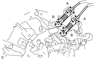
Connect the transmission control cable assembly to the control bracket assembly with 2 new clips (A).
-
Connect the transmission control cable assembly to the manual transaxle assembly with the 2 clips (B).
-
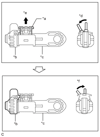
*a Lock Piece *b Stopper *c Adjuster Case *d Twist the stopper *e Pull out *f Return the stopper Release the lock of the transmission control select cable length adjustment structure.
-
Twist the stopper.
-
Pull the lock piece outward from the adjuster case to release the lock.
-
Return the stopper.
-
-
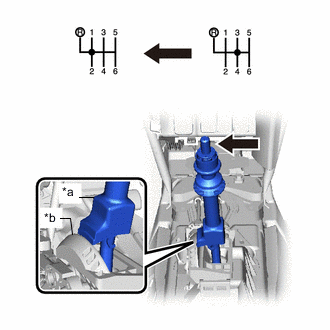
Engage the 2 claws to install the transmission control cable assembly to the floor shift lever assembly.
-
Connect the transmission control shift cable to the floor shift lever assembly.
-
Connect the transmission control select cable to the floor shift lever assembly with the clip.
Note
-
Make sure the lock piece of the transmission control select cable length adjustment structure is facing upward when the transmission control select cable is connected.
-
Make sure that the transmission control select cable is securely installed.
-
-
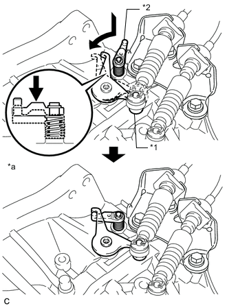
*1 Outer Lever *2 Reverse Restrict Pin Assembly *a Secured Hook the outer lever of the manual transaxle assembly to the reverse restrict pin assembly to secure it.
-
*a Slider Shaft *b Cam Wall Push the slider shaft against the cam wall.
Note
-
Do not pull up the slider shaft.
-
When adjusting the transmission control select cable, make sure that the shift lever is not in 1st or 2nd.
-
-
Lock the transmission control select cable length adjustment structure.
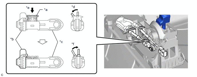
*a Lock Piece *b Stopper *c Adjuster Case *d Twist the stopper *e Push *f Return the stopper
-
Twist the stopper.
-
Push the lock piece into the adjuster case with slider held against the cam wall.
Note
-
Securely press in the lock piece until the lock engages.
-
When adjusting the transmission control select cable, make sure that the shift lever is not in 1st or 2nd.
-
-
Return the stopper to prevent the lock from being released.
Note
-
Push the lock piece as far as it will go.
-
Confirm whether the transmission control select cable length adjustment structure is locked securely.
-
-
-
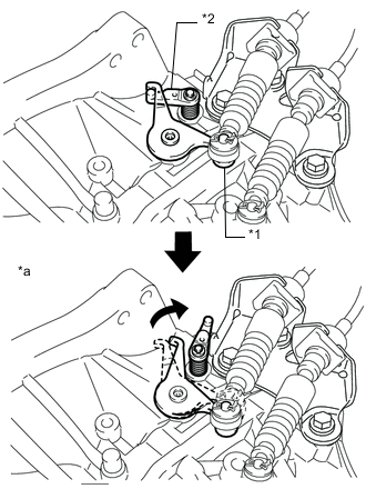
*1 Outer Lever *2 Reverse Restrict Pin Assembly *a Released Move the shift lever to reverse, so that the outer lever can be released.
-
-
INSTALL REAR CONSOLE BOX ASSEMBLY (for Hatchback, Wagon)
-
INSTALL REAR CONSOLE BOX ASSEMBLY (for Sedan)
-
INSTALL NO. 1 FRONT FLOOR HEAT INSULATOR
-
Install the No. 1 front floor heat insulator with the 3 nuts.
- Torque:
- 5.5 N*m { 56 kgf*cm, 49 in.*lbf }
-
-
INSTALL FRONT EXHAUST PIPE ASSEMBLY
-
INSTALL NO. 1 AIR TUBE
-
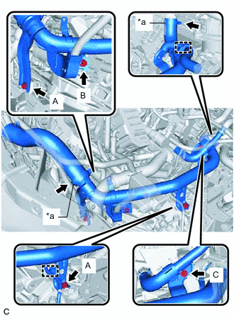
*a Hose Camp Install the No. 1 air tube and tighten the 2 hose clamps.
- Torque:
- 6.5 N*m { 66 kgf*cm, 58 in.*lbf }
Note
One minute after tightening the hose clamp, check that residual torque is 3.2 N*m (33 kgf*cm, 28 in.*lbf) or more.
-
Install the 4 bolts.
- Torque:
- Bolt A
- 20 N*m { 204 kgf*cm, 15 ft.*lbf }
- Bolt B
- 12.5 N*m { 127 kgf*cm, 9 ft.*lbf }
- Bolt C
- 9.8 N*m { 100 kgf*cm, 87 in.*lbf }
-
Connect the 2 wire harness clamps to the manual transaxle assembly.
-
-
INSTALL AIR CLEANER CASE SUB-ASSEMBLY
-
INSTALL AIR CLEANER CAP SUB-ASSEMBLY
-
INSTALL BATTERY
-
INSTALL NO. 1 ENGINE COVER (w/ No. 1 Engine Cover)
-
CONNECT CABLE TO NEGATIVE BATTERY TERMINAL