DIFFERENTIAL CASE REASSEMBLY

PROCEDURE
-
INSTALL FRONT DIFFERENTIAL SIDE GEAR
-
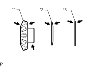
*1 Front Differential Side Gear *2 Conical Spring *3 Front No. 1 Differential Side Gear Thrust Washer 
Gear Oil Coat the front differential side gear, front No. 1 differential side gear thrust washer and conical spring with gear oil.
-
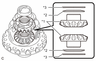
*1 Front Differential Side Gear *2 Conical Spring *3 Front No. 1 Differential Side Gear Thrust Washer Install the 2 front differential side gears, 2 front No. 1 differential side gear thrust washers and 2 conical springs to the front No. 1 differential case sub-assembly.
Note
-
Do not drop the front differential side gear, front No. 1 differential side gear thrust washer and conical spring.
-
Make sure that the conical spring is installed in the correct orientation.
-
-
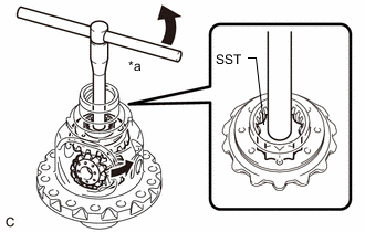
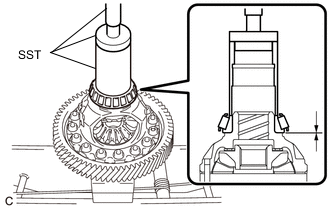
Set SST as shown in the illustration and tighten it.
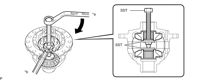
*a Turn *b Hold - SST
- 09528-52010 ( 09953-05010, 09528-05010 )
Note
Do not overtighten SST, as doing so will damage the front differential side gear, conical spring, front differential side gear thrust washer and front No. 1 differential case sub-assembly.
Tech Tips
-
Tighten SST to create the necessary clearance to install the front differential pinions.
-
When installing the front differential pinions, do not overtighten SST, as it is necessary to rotate the front differential side gears.
-
Gear Oil Coat the front differential pinion and front differential pinion thrust washer with gear oil.
-
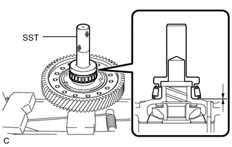
*a Turn Using SST as shown in the illustration, rotate the front differential side gear and install the 2 front differential pinions and 2 front differential pinion thrust washers.
- SST
- 09528-52010 ( 09528-05030 )
CAUTION:
Be careful not to catch your fingers between the front differential pinion and front No. 1 differential case sub-assembly.
Note
Do not drop the front differential pinion and front No. 1 differential pinion thrust washer.
-
-
INSPECT FRONT DIFFERENTIAL PINION BACKLASH
-
INSTALL FRONT NO. 1 DIFFERENTIAL PINION SHAFT
-
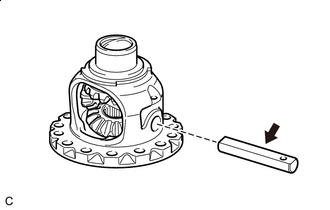
Gear Oil Coat a front No. 1 differential pinion shaft with gear oil.
-
Install the front No. 1 differential pinion shaft to the front No. 1 differential case sub-assembly so that the hole for the front differential pinion shaft straight pin is aligned with the hole in the front No. 1 differential case sub-assembly.
-
-
INSPECT FRONT NO. 1 DIFFERENTIAL CASE SUB-ASSEMBLY
-
INSTALL FRONT DIFFERENTIAL PINION SHAFT STRAIGHT PIN
-
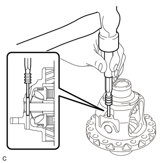
Using a 5 mm pin punch and hammer, install the front differential pinion shaft straight pin to the front No. 1 differential case sub-assembly.
-
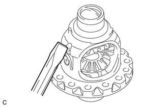
Using a chisel and hammer, stake the front No. 1 differential case sub-assembly.
-
-
INSTALL FRONT DIFFERENTIAL RING GEAR
-
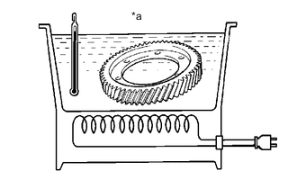
*a 90 to 100°C (194 to 212°F) Using a heater, heat the front differential ring gear to 90 to 100°C (194 to 212°F).
-
Clean the contact surface of the front No. 1 differential case sub-assembly.
-
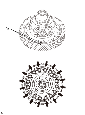
*a Matchmark While aligning the matchmarks, quickly install the front differential ring gear to the front No. 1 differential case sub-assembly with the 16 bolts.
- Torque:
- 106 N*m { 1081 kgf*cm, 78 ft.*lbf }
-
-
INSTALL FRONT DIFFERENTIAL CASE FRONT TAPERED ROLLER BEARING
-
Using SST and a press, install a new front differential case front tapered roller bearing to the front No. 1 differential case sub-assembly.
- SST
- 09523-36010
- 09950-60010 ( 09951-00460, 09951-00560, 09952-06010 )
- 09950-70010 ( 09951-07150 )
-
-
INSTALL FRONT DIFFERENTIAL CASE REAR TAPERED ROLLER BEARING
-
Using SST and a press, install a new front differential case rear tapered roller bearing to the front No. 1 differential case sub-assembly.
- SST
- 09554-22010
-