OUTPUT SHAFT REASSEMBLY

PROCEDURE
-
INSTALL NEEDLE ROLLER BEARING
-
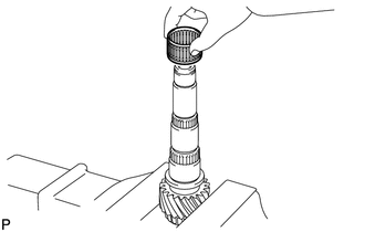
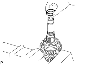
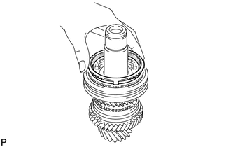
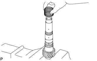
Coat the needle roller bearing with gear oil and install it to the No. 2 output shaft.
-
-
INSTALL REVERSE DRIVEN GEAR
-
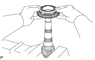
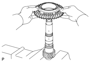
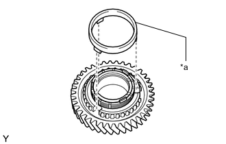
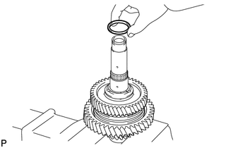
Coat the reverse driven gear with gear oil and install it to the No. 2 output shaft.
-
-
INSTALL NO. 4 TRANSMISSION CLUTCH HUB
-
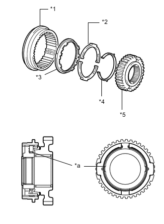
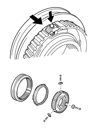
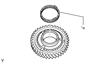
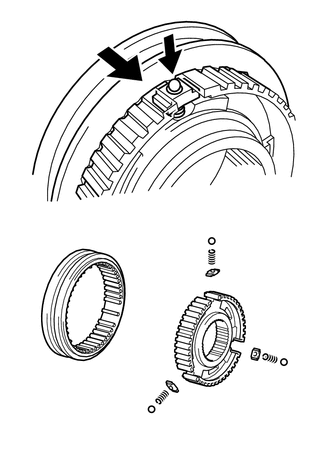
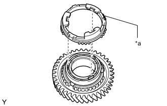
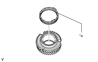
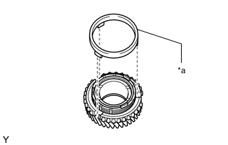
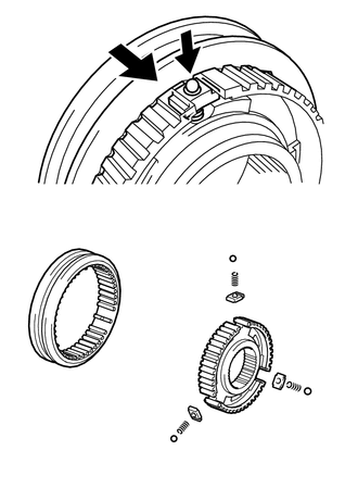
*1 No. 4 Transmission Hub Sleeve *2 Shifting Key *3 Reverse Driven Gear Synchronizer Ring *4 Key Spring *5 No. 4 Transmission Clutch Hub *a Claw Install the reverse driven gear synchronizer ring, key spring and shifting key to the No. 4 transmission clutch hub.
Tech Tips
-
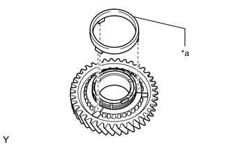
Install the shifting key with the grooves on the No. 4 transmission clutch hub side.
-
Install the key spring with the claw on the No. 4 transmission clutch hub side.
-
Refer to the illustration when installing the key spring and shifting key.
-
-
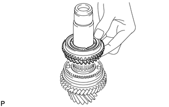
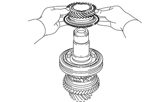
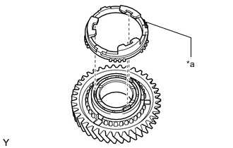
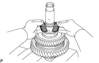
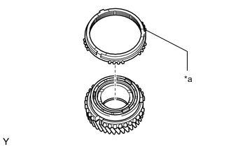
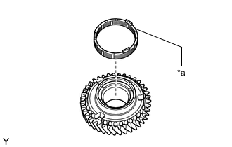
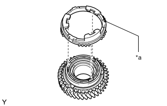
Install the No. 4 transmission hub sleeve to the reverse driven gear as shown in the illustration.
-
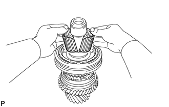
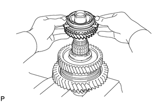
Coat the No. 4 transmission clutch hub with gear oil and install it to the No. 2 output shaft.
-
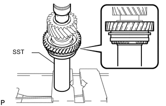
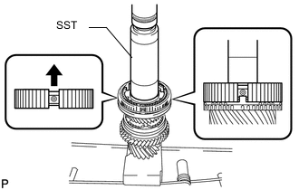
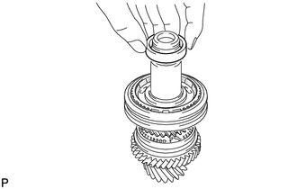
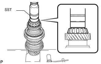
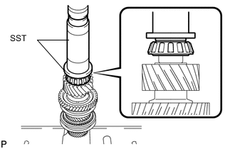
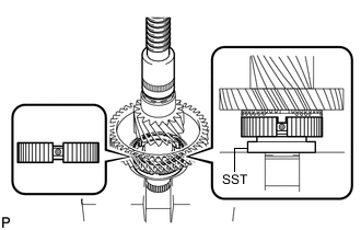
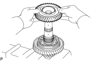
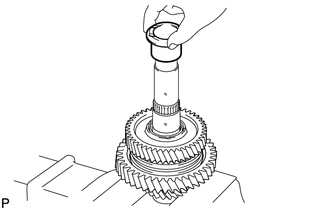
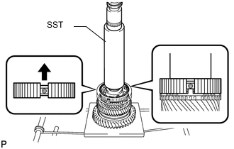
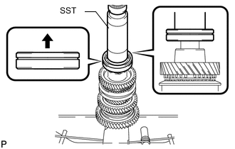
Using SST and a press, install the reverse driven gear and No. 4 transmission clutch hub to the No. 2 output shaft.
- SST
- 09308-14010
Note
After installation, make sure that the gear and synchronizer ring move smoothly.
Tech Tips
Make sure that the protruding part on the reverse driven gear synchronizer ring is fitted into the groove of the No. 4 transmission clutch hub.
-
-
INSTALL SHAFT SNAP RING
-
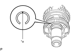
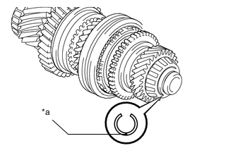
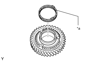
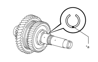
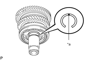
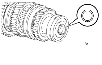
*a Mark Select a new shaft snap ring, using the table below, that makes the thrust clearance of the No. 4 transmission clutch hub less than 0.1 mm (0.00394 in.).
Shaft Snap Ring Thickness: Mark Thickness mm (in.) Mark Thickness mm (in.) A 2.25 to 2.30 (0.0886 to 0.0906) E 2.45 to 2.50 (0.0965 to 0.0984) B 2.30 to 2.35 (0.0906 to 0.0925) F 2.50 to 2.55 (0.0984 to 0.1004) C 2.35 to 2.40 (0.0925 to 0.0945) G 2.55 to 2.60 (0.1004 to 0.1024) D 2.40 to 2.45 (0.0945 to 0.0965) H 2.60 to 2.65 (0.1024 to 0.1043) -
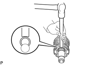
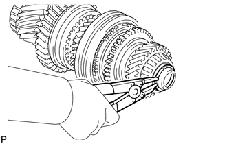
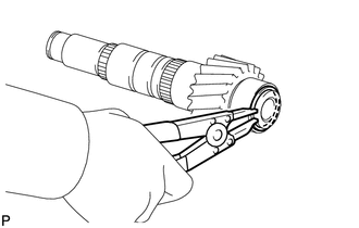
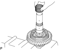
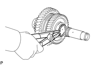
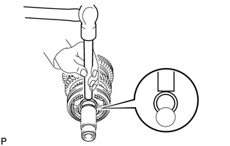
Using a brass bar and hammer, tap the shaft snap ring to the No. 2 output shaft.
-
-
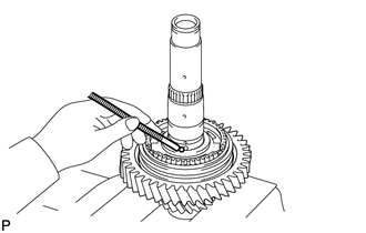
INSPECT REVERSE DRIVEN GEAR THRUST CLEARANCE
-
INSPECT REVERSE DRIVEN GEAR RADIAL CLEARANCE
-
INSTALL 5TH DRIVEN GEAR
-
Install the spacer to the No. 2 output shaft.
-
Coat the needle roller bearing with gear oil and install it to the No. 2 output shaft.
-
Install the spacer to the No. 2 output shaft.
-
Coat the 5th driven gear with gear oil and install it to the No. 2 output shaft.
-
-
INSTALL NO. 3 TRANSMISSION CLUTCH HUB
-
Apply gear oil to the No. 3 transmission hub sleeve and No. 3 transmission clutch hub.
-
Install the No. 3 transmission hub sleeve to the No. 3 transmission clutch hub.
-
Install the 3 No. 1 synchromesh shifting keys to the No. 3 transmission clutch hub.
-
Install the 3 synchronizer shifting key springs to the No. 3 transmission clutch hub.
-
Place the balls in the holes of the No. 1 synchromesh shifting keys and install the No. 3 transmission hub sleeve while pushing in the balls.
Note
Take care to prevent the balls from scattering.
-
Coat the 5th driven gear synchronizer ring with gear oil and install it to the 5th driven gear.
-
Using SST and a press, install the No. 3 transmission clutch hub to the No. 2 output shaft.
- SST
- 09308-14010
Note
After installation, make sure that the gear and synchronizer ring move smoothly.
Tech Tips
Make sure that the protruding part on the 5th driven gear synchronizer ring is fitted into the groove of the No. 3 transmission clutch hub.
-
-
INSTALL SHAFT SNAP RING
-
*a Mark Select a new shaft snap ring, using the table below, that makes the thrust clearance of the No. 3 transmission clutch hub less than 0.1 mm (0.00394 in.).
Shaft Snap Ring Thickness: Mark Thickness mm (in.) Mark Thickness mm (in.) 1 2.25 to 2.30 (0.0886 to 0.0906) 4 2.40 to 2.45 (0.0945 to 0.0965) 2 2.30 to 2.35 (0.0906 to 0.0925) 5 2.45 to 2.50 (0.0965 to 0.0984) 3 2.35 to 2.40 (0.0925 to 0.0945) 6 2.50 to 2.55 (0.0984 to 0.1004) -
Using a brass bar and hammer, tap the shaft snap ring to the No. 2 output shaft.
-
-
INSPECT 5TH DRIVEN GEAR THRUST CLEARANCE
-
INSPECT 5TH DRIVEN GEAR RADIAL CLEARANCE
-
INSTALL 6TH DRIVEN GEAR
-
Install the spacer to the No. 2 output shaft.
-
Coat the needle roller bearing with gear oil and install it to the No. 2 output shaft.
-
Coat the 6th driven gear synchronizer ring with gear oil and install it to the No. 3 transmission clutch hub.
-
Coat the 6th driven gear with gear oil and install it to the No. 2 output shaft.
-
-
INSTALL NO. 2 OUTPUT SHAFT REAR BEARING
-
Using SST and a press, install the No. 2 output shaft rear bearing to the No. 2 output shaft.
- SST
- 09710-04071
Note
After installation, make sure that the gear and synchronizer ring move smoothly.
-
-
INSTALL NO. 2 OUTPUT SHAFT BEARING SNAP RING
-
*a Mark Select a new No. 2 output shaft bearing snap ring, using the table below, that makes the thrust clearance of the No. 2 output shaft rear bearing less than 0.1 mm (0.00394 in.).
No. 2 Output Shaft Bearing Snap Ring Thickness: Mark Thickness mm (in.) Mark Thickness mm (in.) B 1.85 to 1.90 (0.0728 to 0.0748) 0 2.05 to 2.10 (0.0807 to 0.0827) C 1.90 to 1.95 (0.0748 to 0.0768) 1 2.10 to 2.15 (0.0827 to 0.0846) D 1.95 to 2.00 (0.0768 to 0.0787) 2 2.15 to 2.20 (0.0846 to 0.0866) E 2.00 to 2.05 (0.0787 to 0.0807) - - -
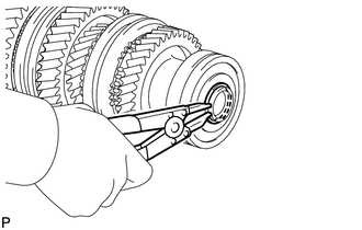
Using a snap ring expander, install the No. 2 output shaft bearing snap ring to the No. 2 output shaft.
-
-
INSPECT 6TH DRIVEN GEAR THRUST CLEARANCE
-
INSPECT 6TH DRIVEN GEAR RADIAL CLEARANCE
-
INSTALL NO. 2 OUTPUT SHAFT FRONT BEARING
-
Using SST and a press, install the No. 2 output shaft front bearing to the No. 2 output shaft.
- SST
- 09309-37010
- 09506-30012
-
-
INSTALL OUTPUT SHAFT FRONT BEARING INNER RACE
-
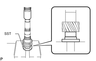
Using SST and a press, install the output shaft front bearing inner race to the No. 1 output shaft.
- SST
- 09309-14040
-
-
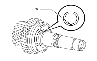
INSTALL OUTPUT SHAFT FRONT BEARING SHAFT SNAP RING
-
Using a snap ring expander, install a new snap ring to the No. 1 output shaft.
-
-
INSTALL 1ST DRIVEN GEAR
-
Coat the needle roller bearing with gear oil and install it to the No. 1 output shaft.
-
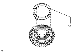
*a Inner Ring Install the inner ring to the 1st driven gear.
-
*a Middle Ring Install the middle ring to the 1st driven gear.
-
*a Outer Ring Install the outer ring to the 1st driven gear.
-
Coat the 1st driven gear with gear oil and install it to the No. 1 output shaft.
-
-
INSTALL NO. 1 TRANSMISSION CLUTCH HUB
-
Apply gear oil to the No. 1 transmission hub sleeve and No. 1 transmission clutch hub.
-
Install the No. 1 transmission hub sleeve to the No. 1 transmission clutch hub.
-
Install the 3 No. 1 synchromesh shifting keys to the No. 1 transmission clutch hub.
-
Install the 3 synchronizer shifting key springs to the No. 1 transmission clutch hub.
-
Place the balls in the holes of the No. 1 synchromesh shifting keys and install the No. 1 transmission hub sleeve while pushing in the balls.
Note
Take care to prevent the balls from scattering.
-
Coat the 1st driven gear synchronizer ring set with gear oil.
-
Using SST and a press, install the No. 1 transmission hub sleeve to the No. 1 output shaft.
- SST
- 09726-40010
Note
After installation, make sure that the gear and synchronizer ring move smoothly.
Tech Tips
Make sure that the protruding part on the 1st driven gear synchronizer ring set is fitted into the groove of the No. 1 transmission clutch hub.
-
-
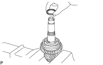
INSTALL 2ND DRIVEN GEAR SYNCHRONIZER RING SET
-
*a Inner Ring Coat the 2nd driven gear synchronizer ring set with gear oil.
-
Install the inner ring to the 2nd driven gear.
-
*a Middle Ring Install the middle ring to the 2nd driven gear.
-
*a Outer Ring Install the outer ring to the 2nd driven gear.
-
-
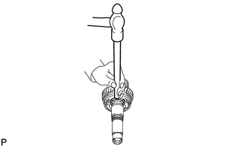
INSTALL SYNCHROMESH SHIFTING KEY BALL
-
Install the synchromesh shifting key ball to the No. 1 output shaft.
-
-
INSTALL NEEDLE ROLLER BEARING
-
Coat the needle roller bearing with gear oil and install it to the No. 1 output shaft.
-
-
INSTALL 2ND DRIVEN GEAR
-
Coat the 2nd driven gear with gear oil and install it to the No. 1 output shaft.
-
-
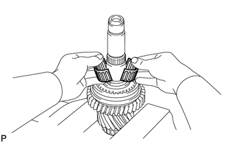
INSTALL 2ND DRIVEN GEAR BEARING INNER RACE
-
Align the groove of the 2nd driven gear bearing inner race with the ball and install the inner race.
-
-
INSTALL OUTPUT SHAFT BEARING SHAFT SNAP RING
-
*a Mark Select a new output shaft bearing shaft snap ring, using the table below, that makes the thrust clearance of the 2nd driven gear bearing inner race less than 0.1 mm (0.00394 in.).
Output Shaft Bearing Shaft Snap Ring Thickness: Mark Thickness mm (in.) Mark Thickness mm (in.) A 2.25 to 2.30 (0.0886 to 0.0906) E 2.45 to 2.50 (0.0965 to 0.0984) B 2.30 to 2.35 (0.0906 to 0.0925) F 2.50 to 2.55 (0.0984 to 0.1004) C 2.35 to 2.40 (0.0925 to 0.0945) G 2.55 to 2.60 (0.1004 to 0.1024) D 2.40 to 2.45 (0.0945 to 0.0965) H 2.60 to 2.65 (0.1024 to 0.1043) -
Using a snap ring expander, install the output shaft bearing shaft snap ring to the No. 1 output shaft.
Tech Tips
Do not damage the journal surface of the No. 1 output shaft.
-
-
INSPECT 1ST DRIVEN GEAR THRUST CLEARANCE
-
INSPECT 1ST DRIVEN GEAR RADIAL CLEARANCE
-
INSPECT 2ND DRIVEN GEAR THRUST CLEARANCE
-
INSPECT 2ND DRIVEN GEAR RADIAL CLEARANCE
-
INSTALL 4TH DRIVEN GEAR
-
Install the spacer to the No. 1 output shaft.
-
Coat the needle roller bearing with gear oil and install it to the No. 1 output shaft.
-
*a Inner Ring Install the inner ring to the 4th driven gear.
-
*a Middle Ring Install the middle ring to the 4th driven gear.
-
*a Outer Ring Install the outer ring to the 4th driven gear.
-
Coat the 4th driven gear with gear oil and install it to the No. 1 output shaft.
-
-
INSTALL NO. 2 TRANSMISSION CLUTCH HUB
-
Apply gear oil to the No. 2 transmission hub sleeve and No. 2 transmission clutch hub.
-
Install the No. 2 transmission hub sleeve to the No. 2 transmission clutch hub.
-
Install the 3 No. 1 synchromesh shifting keys to the No. 2 transmission clutch hub.
-
Install the 3 synchronizer shifting key springs to the No. 2 transmission clutch hub.
-
Place the balls in the holes of the No. 1 synchromesh shifting keys and install the No. 2 transmission hub sleeve while pushing in the balls.
Note
Take care to prevent the balls from scattering.
-
Coat the 4th driven gear synchronizer ring set with gear oil.
-
Using SST and a press, install the transmission clutch hub to the 4th driven gear.
- SST
- 09309-14010
Note
After installation, make sure that the gear and synchronizer ring move smoothly.
Tech Tips
Make sure that the protruding part on the 4th driven gear synchronizer ring set is fitted into the groove of the No. 2 transmission clutch hub.
-
-
INSTALL SHAFT SNAP RING
-
*a Mark Select a new shaft snap ring, using the table below, that makes the thrust clearance of the No. 2 transmission clutch hub less than 0.1 mm (0.00394 in.).
Shaft Snap Ring Thickness: Mark Thickness mm (in.) Mark Thickness mm (in.) 1 2.25 to 2.30 (0.0886 to 0.0906) 4 2.40 to 2.45 (0.0945 to 0.0965) 2 2.30 to 2.35 (0.0906 to 0.0925) 5 2.45 to 2.50 (0.0965 to 0.0984) 3 2.35 to 2.40 (0.0925 to 0.0945) 6 2.50 to 2.55 (0.0984 to 0.1004) -
Using a brass bar and hammer, tap the shaft snap ring to the No. 1 output shaft.
-
-
INSPECT 4TH DRIVEN GEAR THRUST CLEARANCE
-
INSPECT 4TH DRIVEN GEAR RADIAL CLEARANCE
-
INSTALL 3RD DRIVEN GEAR
-
*a Inner Ring Coat the 3rd driven gear synchronizer ring set with gear oil.
-
Install the inner ring to the 3rd driven gear.
-
*a Middle Ring Install the middle ring to the 3rd driven gear.
-
*a Outer Ring Install the outer ring to the 3rd driven gear.
-
Coat the needle roller bearing with gear oil and install it to the No. 1 output shaft.
-
Install the spacer to the No. 1 output shaft.
-
Coat the 3rd driven gear with gear oil and install it to the No. 1 output shaft.
-
-
INSTALL OUTPUT SHAFT REAR BEARING
-
Using SST and a press, install the output shaft rear bearing to the No. 1 output shaft.
- SST
- 09308-14010
Note
After installation, make sure that the gear and synchronizer ring move smoothly.
Tech Tips
When pressing in the bearing, apply force only to the inner race. Do not apply force to the seal.
-
-
INSTALL OUTPUT SHAFT BEARING SHAFT SNAP RING
-
*a Mark Select a new output shaft bearing shaft snap ring, using the table below, that makes the thrust clearance of the output shaft rear bearing less than 0.1 mm (0.00394 in.).
Output Shaft Bearing Shaft Snap Ring Thickness: Mark Thickness mm (in.) Mark Thickness mm (in.) B 1.85 to 1.90 (0.0728 to 0.0748) 0 2.05 to 2.10 (0.0807 to 0.0827) C 1.90 to 1.95 (0.0748 to 0.0768) 1 2.10 to 2.15 (0.0827 to 0.0846) D 1.95 to 2.00 (0.0768 to 0.0787) 2 2.15 to 2.20 (0.0846 to 0.0866) E 2.00 to 2.05 (0.0787 to 0.0807) - - -
Using a snap ring expander, install the output shaft bearing shaft snap ring to the No. 1 output shaft.
-
-
INSPECT 3RD DRIVEN GEAR THRUST CLEARANCE
-
INSPECT 3RD DRIVEN GEAR RADIAL CLEARANCE