TRANSMISSION CONTROL CABLE INSTALLATION
PROCEDURE
-
INSTALL TRANSMISSION CONTROL CABLE ASSEMBLY
-
Pass the transmission control cable assembly into the vehicle and install the transmission control cable assembly to the vehicle body with the 2 nuts.
- Torque:
- 5.0 N*m { 51 kgf*cm, 44 in.*lbf }
-
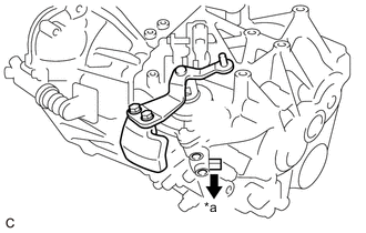
Connect the transmission control cable assembly to the rear engine mounting insulator with the bolt.
- Torque:
- 5.0 N*m { 51 kgf*cm, 44 in.*lbf }
-
Connect the transmission control cable assembly to the control cable bracket with 2 new clips.
-
Connect the transmission control cable assembly to the manual transaxle assembly with the 2 clips.
-
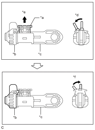
*a Lock Piece *b Stopper *c Adjuster Case *d Twist the stopper *e Pull Out *f Return the stopper Release the lock of the transmission control select cable length adjustment structure.
-
Twist the stopper.
-
Pull the lock piece outward from the adjuster case to release the lock.
-
Return the stopper.
-
-
Engage the 2 claws to connect the transmission control cable assembly to the floor shift lever assembly.
-
Connect the transmission control shift cable to the floor shift lever assembly.
-
Connect the transmission control select cable to the floor shift lever assembly and install the clip.
Note
-
Make sure the lock piece of the transmission control select cable length adjustment structure is facing upward when the transmission control select cable is connected.
-
Make sure that the transmission control select cable is securely installed.
-
-
*a Press *b Press and Hold *c Push in the shift and select lever pin Pressing the shift and select lever shaft and shift and select lever pin, push in the shift and select lever pin and check that the shift and select lever shaft is secured at the 1st-2nd gear (the shaft comes to a stop at the position 8 mm (0.315 in.) below the N position).
-
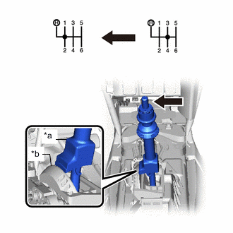
*a Slider Shaft *b Cam Wall Push the slider shaft against the cam wall.
Note
-
Do not pull up the slider shaft.
-
When adjusting the transmission control select cable, make sure that the shift lever is not 1st or 2nd.
-
-
Lock the transmission control select cable length adjustment structure.
-
Twist the stopper.
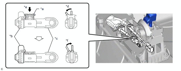
*a Lock Piece *b Stopper *c Adjuster Case *d Twist the stopper *e Push *f Return the stopper -
Push the lock piece into the adjuster case with slider held against the cam wall.
Note
-
Securely press in the lock piece until the lock engages.
-
When adjusting the transmission control select cable, make sure that the shift lever is not in 1st or 2nd.
-
-
Return the stopper to prevent the lock from being released.
Note
-
Push the lock piece as far as it will go.
-
Confirm whether the transmission control select cable length adjustment structure is locked securely.
-
-
-
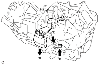
*a Pull Release the shift and select lever pin that secures the shift and select lever shaft.
-
Pull the shift and select lever pin toward the front left side of the vehicle.
-
-
-
INSTALL REAR CONSOLE BOX ASSEMBLY
-
INSTALL FRONT NO. 1 FLOOR HEAT INSULATOR
-
Install the front No. 1 floor heat insulator to the vehicle body with the 3 nuts.
- Torque:
- 5.5 N*m { 56 kgf*cm, 49 in.*lbf }
-
-
INSTALL NO. 1 AIR TUBE ASSEMBLY
-
Install the No. 1 air tube assembly to the manual transaxle assembly with the 2 bolts.
- Torque:
- 20 N*m { 204 kgf*cm, 15 ft.*lbf }
-
Connect the outlet heater water hose to the No. 2 radiator pipe, and slide the clamp to secure it.
-
Connect the water hose sub-assembly to the No. 1 radiator pipe, and slide the clamp to secure it.
-
Engage the clamp to connect the water hose sub-assembly to the compressor outlet elbow.
-
Connect the water by-pass hose assembly to the No. 2 radiator pipe, and slide the clamp to secure it.
-
Connect the radiator hose sub-assembly to the No. 1 radiator pipe, and slide the clamp to secure it.
-
-
CONNECT COMPRESSOR OUTLET ELBOW
-
INSTALL NO. 4 WATER BY-PASS HOSE
-
CONNECT ENGINE WIRE
-
INSTALL AIR CLEANER CASE SUB-ASSEMBLY
-
INSTALL AIR CLEANER CAP SUB-ASSEMBLY WITH AIR CLEANER HOSE ASSEMBLY
-
INSTALL BATTERY CARRIER
-
INSTALL BATTERY
-
INSTALL FRONT EXHAUST PIPE ASSEMBLY
-
ADD ENGINE COOLANT
-
CONNECT CABLE TO NEGATIVE BATTERY TERMINAL
Note
When disconnecting the cable, some systems need to be initialized after the cable is reconnected.
-
INSPECT FOR COOLANT LEAK
-
INSPECT FOR EXHAUST GAS LEAK
-
INSTALL NO. 1 ENGINE COVER
-
INSTALL NO. 1 ENGINE UNDER COVER