MANUAL TRANSAXLE ASSEMBLY INSTALLATION
PROCEDURE
-
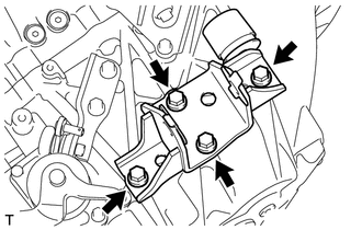
INSTALL REAR ENGINE MOUNTING BRACKET
-
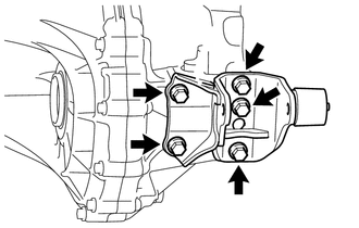
Install the rear engine mounting bracket with the 5 bolts.
- Torque:
- 45 N*m { 459 kgf*cm, 33 ft.*lbf }
-
-
INSTALL FRONT ENGINE MOUNTING BRACKET
-
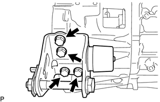
Install the front engine mounting bracket with the 4 bolts.
- Torque:
- 45 N*m { 459 kgf*cm, 33 ft.*lbf }
-
-
INSTALL REAR ENGINE MOUNTING INSULATOR
-
INSTALL MANUAL TRANSAXLE ASSEMBLY
-
Make sure that the dowel pins are not loose, bent, damaged or scratched.
-
While raising and adjusting the angle of the transmission jack, align the manual transaxle assembly with the engine assembly.
Note
Make sure that the manual transaxle assembly does not contact the clutch lines.
-
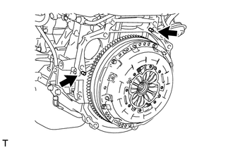
Align the input shaft with the clutch disc and then install the manual transaxle assembly to the engine assembly so that the contact surfaces of the engine assembly and manual transaxle assembly are flat against each other.
-
Temporarily install the manual transaxle assembly with the 6 bolts.
Note
-
Make sure that the manual transaxle assembly does not contact the vehicle body, clutch lines and radiator cooling fan when installing the manual transaxle assembly.
-
Make sure that the wire harness or similar items are not pinched between the contact surfaces.
-
Do not forcibly pry on the manual transaxle assembly when installing it to the engine assembly.
-
Insert the dowel pins into the dowel holes securely so that the contact surfaces of the manual transaxle assembly and engine assembly are flat against each other before tightening the bolts.
-
Do not apply excessive force to the manual transaxle assembly as this will break the input shaft.
-
-
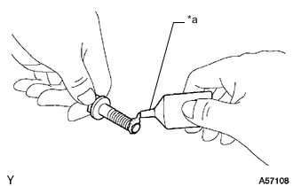
*a Adhesive 1324 Apply adhesive to 2 or 3 threads on the ends of the 4 bolts.
Adhesive Toyota Genuine Adhesive 1324, Three Bond 1324 or equivalent Note
In order to ensure proper installation of the 4 bolts, apply adhesive to the 4 bolts and install them within 10 minutes of adhesive application.
-
Install the engine mounting bracket LH to the manual transaxle assembly with the 4 bolts.
- Torque:
- 64 N*m { 653 kgf*cm, 47 ft.*lbf }
-
Install the engine mounting insulator LH to the vehicle body with the 4 bolts.
- Torque:
- 95 N*m { 969 kgf*cm, 70 ft.*lbf }
-
Slowly raise the engine assembly and manual transaxle assembly using a transmission jack to align the engine mounting bracket LH with the engine mounting insulator LH.
-
Install the through bolt and nut to connect the engine mounting insulator LH to the engine mounting bracket LH.
- Torque:
- 56 N*m { 571 kgf*cm, 41 ft.*lbf }
-
-
TEMPORARILY INSTALL NO. 2 MANIFOLD STAY
-
Using an E14 "TORX" socket wrench, temporarily install the No. 2 manifold stay with the 2 bolts.
-
Temporarily install the nut.
-
-
TEMPORARILY INSTALL STARTER ASSEMBLY
-
Using an E14 "TORX" socket wrench, temporarily install the starter assembly with the 2 bolts.
-
-
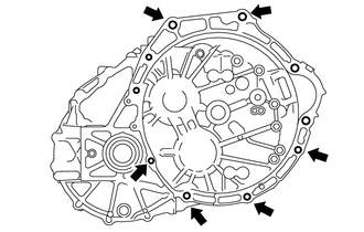
TIGHTEN ENGINE AND TRANSAXLE CONNECTING BOLT
-
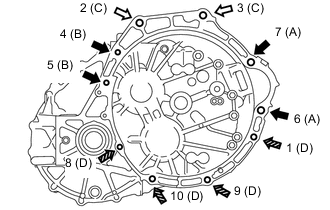

E14 "TORX" Bolt
Bolt length 100 mm (3.94 in.)

E14 "TORX" Bolt
Bolt length 80 mm (3.15 in.)

Bolt
Bolt length 40 mm (1.57 in.)
Tighten the 10 bolts in the order shown in the illustration.
- Torque:
- Bolt (A)
- 64 N*m { 653 kgf*cm, 47 ft.*lbf }
- Bolt (B)
- 79 N*m { 806 kgf*cm, 58 ft.*lbf }
- Bolt (C)
- 64 N*m { 653 kgf*cm, 47 ft.*lbf }
- Bolt (D)
- 24 N*m { 245 kgf*cm, 18 ft.*lbf }
-
Tighten the nut to install the No. 2 manifold stay.
- Torque:
- 19 N*m { 194 kgf*cm, 14 ft.*lbf }
-
-
INSTALL FRONT ENGINE MOUNTING INSULATOR
-
Install the front engine mounting insulator with the through bolt and nut.
- Torque:
- 145 N*m { 1479 kgf*cm, 107 ft.*lbf }
-
-
INSTALL FRONT CROSS MEMBER SUB-ASSEMBLY
-
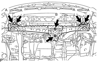
Install the front cross member sub-assembly with the 6 bolts.
- Torque:
- Bolt (A)
- 99 N*m { 1010 kgf*cm, 73 ft.*lbf }
- Bolt (B)
- 95 N*m { 969 kgf*cm, 70 ft.*lbf }
-
Remove the transmission jack.
-
-
INSTALL FRONT SUSPENSION CROSSMEMBER SUB-ASSEMBLY
-
CONNECT WIRE HARNESS
-
Connect the ground cable to the manual transaxle assembly with the bolt.
- Torque:
- 12.5 N*m { 127 kgf*cm, 9 ft.*lbf }
-
Connect the neutral position switch connector.
-
Connect the back-up light switch assembly connector.
-
Connect the wire harness with the 2 bolts.
- Torque:
- 12.8 N*m { 131 kgf*cm, 9 ft.*lbf }
-
-
CONNECT CLUTCH RELEASE CYLINDER ASSEMBLY
-
Connect the clutch release cylinder assembly and clutch flexible hose bracket to the manual transaxle assembly with the 4 bolts.
- Torque:
- 12 N*m { 122 kgf*cm, 9 ft.*lbf }
-
-
INSTALL NO. 1 CLUTCH HOUSING COVER
-
Install the No. 1 clutch housing cover with the 2 bolts.
- Torque:
- 30 N*m { 306 kgf*cm, 22 ft.*lbf }
-
-
CONNECT TRANSMISSION CONTROL CABLE ASSEMBLY
-
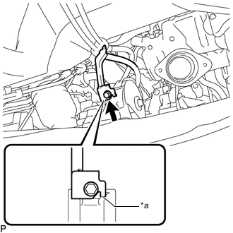
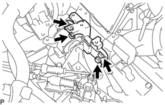
*a Anti-rotation Pin Connect the bracket of the transmission control cable assembly to the rear engine mounting insulator with the bolt.
- Torque:
- 5.0 N*m { 51 kgf*cm, 44 in.*lbf }
Tech Tips
Make sure the anti-rotation pin is contacting the rear engine mount insulator.
-
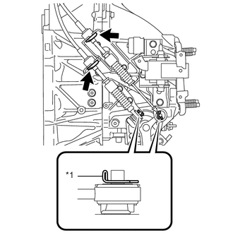
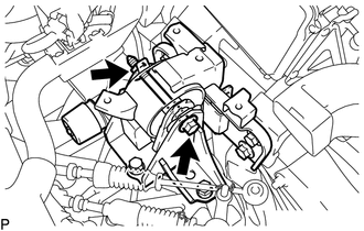
*1 Clip Connect the transmission control cable assembly to the control cable bracket with 2 new clips.
Note
Do not bend the transmission control cable assembly more than necessary.
-
Connect the transmission control cable assembly to the manual transaxle assembly and install the 2 clips to secure it.
-
-
ADJUST TRANSMISSION CONTROL CABLE ASSEMBLY
-
INSTALL NO. 1 AIR TUBE ASSEMBLY
-
Install the No. 1 air tube assembly to the manual transaxle assembly with the 2 bolts.
- Torque:
- 20 N*m { 204 kgf*cm, 15 ft.*lbf }
-
Connect the outlet heater water hose to the No. 2 radiator pipe, and slide the clamp to secure it.
-
Connect the water hose sub-assembly to the No. 1 radiator pipe, and slide the clamp to secure it.
-
Engage the clamp to connect the water hose sub-assembly to the compressor outlet elbow.
-
Connect the water by-pass hose assembly to the No. 2 radiator pipe, and slide the clamp to secure it.
-
Connect the radiator hose sub-assembly to the No. 1 radiator pipe, and slide the clamp to secure it.
-
-
CONNECT NO. 2 AIR HOSE
-
CONNECT COMPRESSOR OUTLET ELBOW
-
INSTALL NO. 4 WATER BY-PASS HOSE
-
CONNECT ENGINE WIRE
-
INSTALL AIR CLEANER BRACKET
-
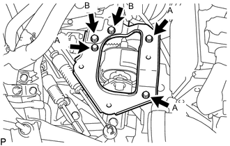
Install the air cleaner bracket with the 5 bolts.
- Torque:
- Bolt (A)
- 7.0 N*m { 71 kgf*cm, 62 in.*lbf }
- Bolt (B)
- 18 N*m { 184 kgf*cm, 13 ft.*lbf }
-
Engage the 3 clamps to install the wire harness.
-
-
INSTALL AIR CLEANER CASE SUB-ASSEMBLY
-
INSTALL AIR CLEANER CAP SUB-ASSEMBLY WITH AIR CLEANER HOSE ASSEMBLY
-
INSTALL DRIVE SHAFT ASSEMBLY
-
INSTALL NO. 1 ENGINE COVER
-
INSTALL STARTER ASSEMBLY
-
INSTALL FRONT EXHAUST PIPE ASSEMBLY
-
ADD ENGINE COOLANT
-
ADD MANUAL TRANSAXLE OIL
-
INSPECT FOR COOLANT LEAK
-
INSPECT FOR OIL LEAK
-
CONNECT CABLE TO NEGATIVE BATTERY TERMINAL
Note
When disconnecting the cable, some systems need to be initialized after the cable is reconnected.
-
INSPECT FOR EXHAUST GAS LEAK
-
INSTALL REAR ENGINE UNDER COVER LH
-
INSTALL REAR ENGINE UNDER COVER RH
-
INSTALL FRONT LOWER BUMPER ABSORBER
-
INSTALL NO. 1 ENGINE UNDER COVER