MANUAL TRANSAXLE ASSEMBLY INSTALLATION
PROCEDURE
-
INSTALL SPEEDOMETER DRIVEN HOLE COVER SUB-ASSEMBLY
-
Coat a new O-ring with gear oil.
-
Install the O-ring to the speedometer driven hole cover sub-assembly.
-
Install the speedometer driven hole cover sub-assembly to the manual transaxle assembly with the bolt.
- Torque:
- 5.5 N*m { 56 kgf*cm, 49 in.*lbf }
-
-
INSTALL REAR ENGINE MOUNTING BRACKET
-
Install the rear engine mounting bracket to the manual transaxle assembly with the 5 bolts.
- Torque:
- 45 N*m { 459 kgf*cm, 33 ft.*lbf }
-
-
INSTALL FRONT ENGINE MOUNTING BRACKET
-
Install the front engine mounting bracket to the manual transaxle assembly with the 3 bolts.
- Torque:
- 64 N*m { 653 kgf*cm, 47 ft.*lbf }
-
-
INSTALL ENGINE MOUNTING BRACKET LH
-
Apply adhesive to the 4 bolts.
Adhesive Toyota Genuine Adhesive 1324, Three Bond 1324 or equivalent -
Install the engine mounting bracket LH to the manual transaxle assembly with the 4 bolts.
- Torque:
- 64 N*m { 653 kgf*cm, 47 ft.*lbf }
-
-
INSTALL WIRE HARNESS CLAMP BRACKET
-
Install the wire harness clamp bracket to the manual transaxle assembly with the bolt.
- Torque:
- 12.5 N*m { 127 kgf*cm, 9 ft.*lbf }
-
-
INSTALL MANUAL TRANSAXLE ASSEMBLY
-
Check that the 2 knock pins are installed on the engine assembly before installing the manual transaxle assembly.
-
Align the input shaft with the clutch disc and install the manual transaxle assembly to the engine assembly.
-
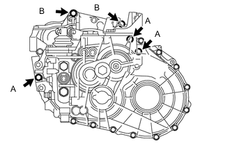
Install the 5 bolts.
- Torque:
- Bolt A
- 46 N*m { 469 kgf*cm, 34 ft.*lbf }
- Bolt B
- 64 N*m { 653 kgf*cm, 47 ft.*lbf }
Note
-
Make sure that the wire harness or similar items are not pinched between the contact surfaces.
-
Do not forcibly pry on the manual transaxle assembly when installing it to the engine assembly.
-
Do not apply excessive force to the manual transaxle assembly as this will break the input shaft.
-
Make sure that the knock pins fit securely into the holes when installing the manual transaxle assembly to the engine assembly.
-
Make sure that the contact surfaces of the engine assembly and manual transaxle assembly are flat against each other before tightening the bolts.
-
-
INSTALL STIFFENER PLATE LH
-
Install the stiffener plate LH to the engine assembly and manual transaxle assembly with the 4 bolts.
- Torque:
- 46 N*m { 469 kgf*cm, 34 ft.*lbf }
-
-
INSTALL STIFFENER PLATE RH
-
Install the stiffener plate RH to the engine assembly and manual transaxle assembly with the 4 bolts.
- Torque:
- 46 N*m { 469 kgf*cm, 34 ft.*lbf }
-
-
INSTALL OIL PAN INSULATOR
-
Install the oil pan insulator to the stiffener plate RH and stiffener plate LH with the 2 bolts.
- Torque:
- 9.0 N*m { 92 kgf*cm, 80 in.*lbf }
-
-
INSTALL AIR TUBE SUPPORT
-
Install the air tube support to the manual transaxle assembly with the 2 bolts.
- Torque:
- 30 N*m { 306 kgf*cm, 22 ft.*lbf }
-
-
INSTALL STARTER ASSEMBLY
-
INSTALL NO. 1 AIR TUBE
-
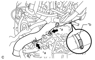
*a Bolt *b Hose Clamp Install the No. 1 air tube to the air tube support and hose with the 2 bolts and tighten the hose clamp.
- Torque:
- Bolt
- 20 N*m { 204 kgf*cm, 15 ft.*lbf }
- Hose clamp
- 6.5 N*m { 66 kgf*cm, 58 in.*lbf }
-
-
CONNECT ENGINE WIRE
-
Connect the engine wire to the manual transaxle assembly with the 2 clamps.
-
Install the engine wire to the manual transaxle assembly with the bolt.
- Torque:
- 12.5 N*m { 127 kgf*cm, 9 ft.*lbf }
-
Connect the 3 clamps to the manual transaxle assembly.
-
Connect the park/neutral position switch assembly connector.
-
Connect the back-up light switch assembly connector.
-
-
TEMPORARILY TIGHTEN REAR ENGINE MOUNTING INSULATOR
-
INSTALL ENGINE ASSEMBLY WITH TRANSAXLE